19
4.2
Function and Description of Main Circuit Terminal (TM1)
Table 4.2a Function and description of TM1
Terminal
Designatio
Terminal Description
Function
Comments
L1(R)
L2(S)
L3(T)
Input terminals of AC
line power
*4
CC-200 series:
1 phase/ 3 phase, 200-240 VAC +/-
10% *1
50/60 Hz +/- 5%
CC-400 series:
3 phase, 380-460 VAC +/- 10%(not to
exceed)
50/60 Hz +/- 5%
Use L1 and L2
single phase
input
T1(U)
T2(V)
T3(W)
Output terminals
*4
CC-200 series:
3 phase, 0~200-230VAC
CC-400 series:
3 phase, 0~380-460VAC
Never connect
line power to
motor terminals.
P/R
P/N *3
External braking resistor
connection terminals
*4
With the application of successive
braking the inverter braking resistor may
overheat. Please replace the built-in
braking resistor with a resistor of larger
watt rating externally.
Replacement Procedures: *2
* Detach the built in resistor from P/R
terminal and insulate exposed ends.
*Install external resistor with larger
capacity (watt)
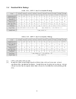
* The standard resistance of inverter
braking resistor is shown in tables 4.2.b,
4.2c, and 4.2d
Used to connect
the optional
external Dynamic
Brake Package.
E
Ground terminal
Earth Grounding
Connect to earth
ground
NOTE:
Connect AC line power to terminals L1 and L2 in single phase application.
*1.
Single phase input only appropriate for CC 204-222 models.
*2.
The braking resistor of smaller CC series is soldered on the PC Board and can not be
replaced. Consult Drivecon for replacement.
*3.
There is no built-in brake unit in CC models of 15HP and larger. An external brake
unit; VFDB and resistor must be added for 100% brake torque.
*4.
Terminations to inverter must be made with either listed field wiring lug kits or listed
crimp type ring terminals.


