


52
Fn46
: Multi-function selection #2
Fn47
: Multi-function selection #1
Input terminal #11 of TM2 or #5 of TB1 for 120VAC (24VAC) input is classified as
multi-function terminal #2. Input terminal #7 of TM2 or #4 of TB1 for 120VAC
(24VAC) input is classified as multi-function terminal #1. The function of these termi-
nals can be defined to one of 9 different functions listed below in table 5.3i.
Frequency set points
Programs
Fn1
(1)
Fn1
(2)
Fn1
(3)
Fn2
(4)
Fn2
(5)
Fn46=2, Fn48=1
6
15
30
45
60
Fn46=2,
Fn48=10
0.6
1.5
3
4.5
6
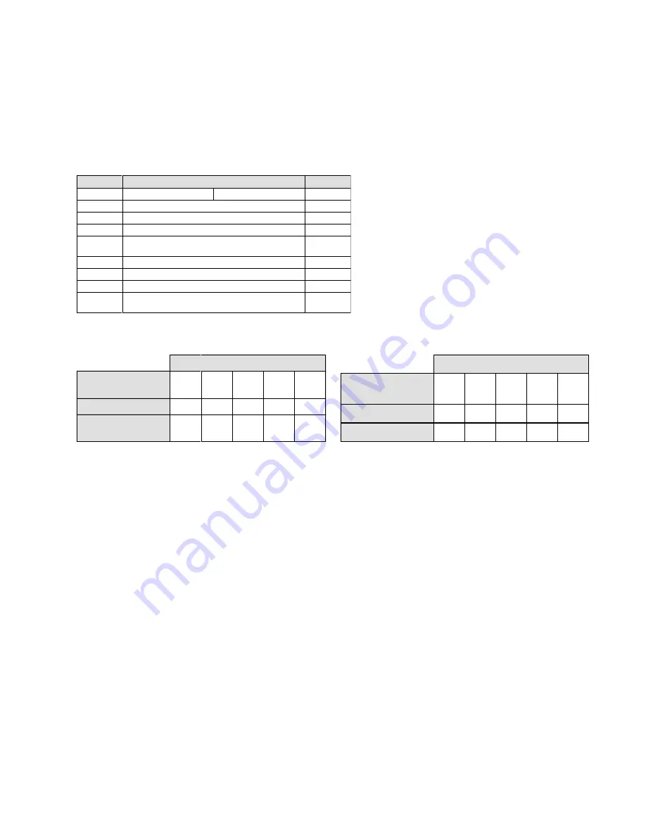
Table 5.3k 'Speed Commander' Functions
Table 5.3j 'Inch Commander' Function
Frequency set points
Programs
Fn1
(1)
Fn1
(2)
Fn1
(3)
Fn2
(4)
Fn2
(5)
Fn46=3, Fn3=1*
6
15
30
45
60
Fn46=3, Fn3=2*
6
15
30
30
30
* With terminal 11 of TM2 or terminal 5 of TB1 active.
* With terminal 11 of TM2 or terminal 5 of TB1 active.
d) 'Speed Commander' operates in conjunction with code
Fn3
as a maximum speed
limiter set by the value of
Fn47
by dividing Fmax by value of
Fn3
and setting this value
as Fmax as shown in table 5.3k.
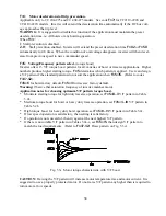
e) 'Limit Commander' operates as a single point travel limit command such that the
direction being traveled will be locked out and inverter will either coast to a stop if
Fn46=4
or ramp down to a stop if
Fn46=5
. Only opposite direction will operate until
limit switch is once again opened.
TrL
will be displayed on LED display while limit
switch is closed and direction command is neutral or the direction that is locked out is
selected. Should the power to the inverter be turned off and the limit switch is closed, the
inverter will operate at the first speed point (
Fn17
) in either direction until the limit
switch is opened. After which point full speed operation will resume in both directions.
If the limit switch input is not opened within 20 seconds the direction selected will be
locked out. The opposite direction will be capable of operation for up to 20 seconds at
low speed or until the limit opens.
WARNING:
The Limit Commander function is not to be used for hoist motions.
Drivecon recommends limits inserted in each direction.
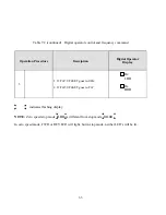
Table 5.3i
)Q
Function
)Q
5th speed command
4th speed command
Fault reset input
’Inch Command’ creep speed operation
’Speed Commander’ maximum speed limiter
’Limit Commander’ travel limit input. (coast to
stop)
’Limit Commander’ travel limit input. (ramp to stop)
Emergency stop input (N.C. to run)
Base block input (N.O. to run)
Secondary acceleration and deceleration
selection.
a) Fault reset allows VFD fault reset
from a switch closure.
b) 4th and 5th speed allows 4th and 5th
speed operation when using 5 preset
speeds.
c) 'Inch Command' operates in conjunc-
tion with code
Fn48
as a speed reducer
set by the values of
Fn48
as shown
below in table 5.3j.


