Section 3 Standard Wiring of Crane Commander
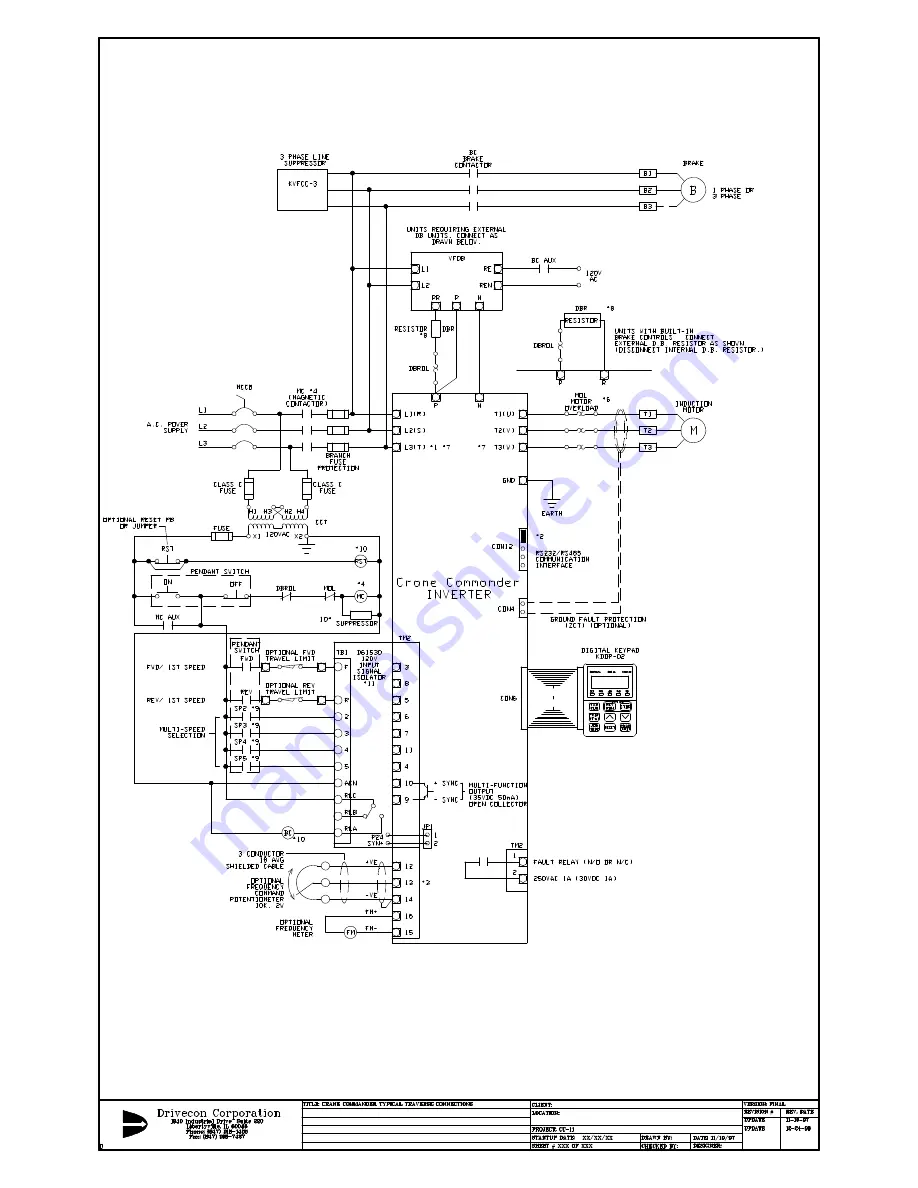
3.1 Typical Traverse
interconnection
diagram. (Some devices are optional and may not be required in all cases.)
Fig. 3.1
Please refer to Appendix E of this manual for
'B' size drawings of Fig. 3.1. Also provided
is a disk with Autocad™ R13 (.DWG and .DXF)
drawings for your use.
WARNING: Wiring diagrams differ per application.
Please consult system wiring diagrams or Drivecon Corporation.
Insure wiring conforms with all applicable industry and safety standards.
of inverter's control wiring or terminal ACN of D61530 120V isolator.
4. MC use is optional depending upon application, if not used: wire motor overload contacts in series with terminal 4 common
3. Do not connect wiper of frequency command potentiometer to terminal 12 or 14 of TM2. This will damage the inverter.
NOTE:
2. Use jumper to short PIN1 and PIN2 when CON12 is not used.
1. In single phase applications, connect AC power supply to L1 and L2 of inverter.
7. See page 13, 14 for tightening torque values of TM1 screw terminals.
8. Use high temperature wire near resistor elements such as SRML.
9. Terminals SP2-SP5 are multi-function terminals which can be defined to use preferences.
10. All coils are to have suppressors.
11. Specify part number D61531 for 24VAC control voltage.
12. Terminations to inverter must be made with either listed
field wiring lug kits or listed crimp type ring terminals.
5. Built in brake unit not provided on units CC-211- or CC4110 and larger. Connect braking unit and resistors as shown.
Consult factory for details.
6. See page 15 section 3.5 on required motor thermal overload relay. NEC requires thermal overload protection for motor branch circuits.
13. Ground fault protection is standard on start only. Optional Ground Fault protection
while running is shown.

