background image

70

b.

Troubleshooting Procedure

(1)

Motor doesn't run

Is there any

display on

keyboard?

Is inverter under

"RUN" command?

Is there any fault

showing on

display?

Is there any output

on T1(U), T2(V),

and T3(W)?

Are output voltages

T1(U), T2(V),

T3(W)  balanced?

*Motor overloaded or shaft locked

*Motor is damaged

*Defective wiring

Is the input power

L1(R), L2(S), L3(T)

stable?

Can MCCB be

turned on?

Is MCCB on?

Press "RUN" to

operate motor

Refer to fault

indication to do

troubleshooting

-Unstable  power

source

-Defective  wiring

Inverter damaged

Short circuits

Inverter damaged

Inverter  damaged

Are parameters set

correctly?

Correct param-

eters

NO

YES

YES

YES

YES

YES

NO

YES

YES

NO

NO

NO

NO

NO

NO

NO

The output voltage is balanced when it is +/- 3% of maximum

output voltage without load.

*1  Without keypad, check if LED 101 is on.

YES

NO

*1

DANGER!

Hazardous  voltage  within  can  cause  serious  injury  or  death.

Operating drive from keypad may disable  safety circuits and

result in danger or injury.  Only qualified personnel should work

on this equipment  after familiarization with its operation.  Turn

OFF and lock out power at main panel.  Allow capacitors to bleed

off prior to servicing.

Summary of Contents for Crane Commander ??-204

Page 1: ...the Sine of Quality INSTRUCTION MANUAL Series AC Crane Hoist Drives RANE OMMANDER Rev 2 8 02 0 2 7 2 5 5 9 6 1 2 1 7 5 2 6...

Page 2: ...n 5 Digital operator control 5 1 Introduction and configuration 32 5 2 Function parameter setting 35 5 3 Function code descriptions Fn00 Fn71 36 5 4 Factory default load Quick Set 57 Section 6 Test ru...

Page 3: ...safety practices 2 Is trained in the proper care and use of protective equipment such as rubber gloves hard hat safety glasses or face shields flash clothing etc in accordance with established safety...

Page 4: ...connections or TB1 of D61530 for 120VAC connections refer to interconnection diagram on page 11 and 12 The following functions will be set using the Quick load feature Fn29 0 for hoist Fn29 1 for tra...

Page 5: ...brakes The Crane Commander is suited for CMAA class A D use only WARRANTY Drivecon Corporation warrants that all products manufactured by it to be free from defects in mate rial and or workmanship un...

Page 6: ...put through strict Q C tests at the factory prior to shipment Before unpacking please check the following Please compare the description of the product found on the name plate with your purchase order...

Page 7: ...C 207 215 222 237 CC 407 415 422 437 all rated protected chassis IP00 CC 255 2220 455 4220 all are NEMA1 IP20 Protected from rain and moisture Shielded from direct sunlight Free from metallic particle...

Page 8: ...ODEL CC 204 7 48 7 09 7 60 CC 207 7 48 7 09 7 60 CC 215 9 06 8 66 9 20 CC 222 9 06 8 66 9 20 Fig 2 3a Mounting Dimension of CC 204 222 Please refer to Appendix E of this manual for dimension drawings...

Page 9: ...07 415 422 CC 437 MODEL H CC 237 7 00 CC 407 415 422 6 00 Fig 2 3b Mounting Dimension of CC 237 407 437 Please refer to Appendix E of this manual for dimension drawings on disk Format is AutocadTM R13...

Page 10: ...6 CC 255 CC 455 CC 475 CC 275 Fig 2 3c Mounting Dimension of CC 255 275 455 475 Please refer to Appendix E of this manual for dimension drawings on disk Format is AutocadTM R13 DWG and DXF...

Page 11: ...110 CC 2150 CC 2220 CC 4110 CC 4150 CC 4220 Fig 2 3d Mounting Dimension of CC 2110 2220 4110 4220 Please refer to Appendix E of this manual for dimension drawings on disk Format is AutocadTM R13 DWG a...

Page 12: ...4110 CC 4150 CC 4220 Motor Rating KW 0 4 0 75 1 5 2 2 3 7 5 5 7 5 11 2 15 22 4 Constant Torque Motor Rating HP 2 0 5 1 2 3 5 7 5 10 15 20 30 Constant Torque Rated Current A 1 1 5 2 3 3 8 5 2 8 8 13 1...

Page 13: ...venting 40 Amb t 10 C Model kW CC 204 CC 404 0 4 35 30 1 6 1 2 3 1 085 1 550 CC 207 CC 407 0 75 40 34 4 7 1 2 3 1 131 1 767 CC 215 CC 415 1 5 60 51 6 10 7 2 8 1 689 2 650 CC 222 CC 422 2 2 70 60 2 12...

Page 14: ...z operationable from keypad pushbutton Operation modes Remote 120V terminal input or keypad FWD REV momentary V F Pattern 15 pre defined patterns One Curve programmable Braking torque or equal to 10HP...

Page 15: ...age the inverter NOTE 2 Use jumper to short PIN1 and PIN2 when CON12 is not used 1 In single phase applications connect AC power supply to L1 and L2 of inverter 7 See page 13 14 for tightening torque...

Page 16: ...disk with Autocad R13 DWG and DXF drawings for your use 1 In single phase applications connect AC power supply to L1 and L2 of inverter 7 See page 13 14 for tightening torque values of TM1 screw term...

Page 17: ...y the unit or lead inverter to trip Tables 3 3a and 3 3b shown below provides the suggested rating of MCCB or MC for each of the inverter ratings You should install RC surge absorbers across the coils...

Page 18: ...them should be directly grounded to a common point Please follow the grounding instructions shown in Fig 3 4 WARNING Never ground or connect terminal N of inverter to neutral Table 3 3b CC 4XX Series...

Page 19: ...to inverter output This branch circuit should be fused in accordance with NEC regulations The coil of the brake contactor should be connected to the running relay output provided on the D61530 at ter...

Page 20: ...etween motor and inverter Size festoon according to NEC standards based on inverter ampacity Table 3 7a Specification of reactor for constant torque use 5 impedance Inverter Type Current Amps Inductan...

Page 21: ...Jumper 1 Ground TM1 Main terminal under D61530 1 D61530 120VAC D61531 24VAC isolator Shown detached from TM2 CON6 Connector of digital operator interface CON4 Connector of ground fault protection ZCT...

Page 22: ...strip Caution Use screwdriver to dislodge Do not pull on wires D61530 TB1 D61531 All models F R 2 3 4 5 ACN RLA RLC RLB D61530 120VAC D61531 24VAC isolator Shown detached from TM2 CON4 Connector of gr...

Page 23: ...of larger watt rating externally Replacement Procedures 2 Detach the built in resistor from P R terminal and insulate exposed ends Install external resistor with larger capacity watt The standard res...

Page 24: ...ng torque CC 204 CC 207 CC 207 150 20 285 30 152 CC 215 75 40 103 CC 222 75 40 86 CC 237 CC 255 CC 275 62 100 84 63 52 CC 2110 Without braking resistor or module 15 20 CC 2150 CC 2220 CC 404 CC 407 CC...

Page 25: ...amic brake option 1 2 10HP units require additional external resistor for all heavy duty applications and any CMAA class D uses Internal D B resistor must be disconnected when connecting external resi...

Page 26: ...rake option 1 2 10HP units require additional external resistor for all heavy duty applications and any CMAA class D uses Internal D B resistor must be disconnected when connecting external resistor U...

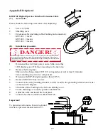
Page 27: ...N 4 3 3 MOUNTING INSTRUCTIONS DANGER Hazardous voltage within can cause serious injury or death Operating drive from keypad may disable safety circuits and result in danger or injury Only qualified pe...

Page 28: ...and connector may result Pry apart where both halves meet with a small flat blade screwdriver 4 3 4 CONNECTION Two directions including first speed 4 extra speeds special functions and reset can be co...

Page 29: ...ontrol operating direction of inverter and connected motor Each direc tion is interlocked electronically Should both directions become energized the inverter will stop according to the selected stoppi...

Page 30: ...SP1 FWD SP1 FWD SP1 8 R REV REV REV SP1 REV SP1 REV SP1 5 2 x x SP2 ACC HOLD 6 3 x x SP3 x ACC 7 4 multi function terminal 1 multi function terminal 1 multi function terminal 1 multi function terminal...

Page 31: ...ct keypad operator control setting see note Fig 4 4g Fn 1 TM2 analog input see note 4 4 5 Timing diagrams of speed command methods The following are timing diagrams explaining the various methods of s...

Page 32: ...ast to stop Ramp to stop DC injection off Fn53 does not equal 0 X 0 Fn54 does not equal 0 0 does not equal 0 Fn55 does not equal 0 X X Table 4 4c Note Codes Fn53 and Fn54 control the method of deceler...

Page 33: ...er or equal to Fn9 Please refer to Fig 4 4l D61530 D61531 is connected to the main PC board by a 2 wire jumper connected to header JP1 on the Crane Commander a Run mode output when Fn8 0 Level of term...

Page 34: ...ing coil DC 1mA frequency meter or 0 10V digital frequency meter Terminal 16 Positive terminal of frequency meter See Figure 4 1a and 4 1b for furthur explanation NOTE Leave jumper pin connected to on...

Page 35: ...V FWD JOG REMOTE STOP FWD RUN REV RUN STOP PRGM Fn JOG MODE RESET READ ENTER E Stop key orange E Stop command in digital operator control mode Red LED lights when motor is forward running Red LED ligh...

Page 36: ...ec 0 1 sec 0 sec 0 5 sec Fn23 Smooth Operator curve Time 2 0 4 sec 0 1 sec 0 sec 0 5 sec Fn24 Jog Frequency 0 180Hz 0 1 Hz 5 Hz 5 Hz Fn25 Master Frequency 0 180Hz 0 1 Hz 5 Hz 5 Hz Fn26 BIAS of TM2 ana...

Page 37: ...sec injection Fn54 DC Braking injection frequency 0 1 10Hz 0 1 Hz 0 2 Hz Fn55 DC Braking level 0 20 0 10 0 5 Fn56 Command Link Baud rate 0 3 2 2 Fn57 Command Link response mode 0 7 1 1 Fn58 Command L...

Page 38: ...nt frequency QG 6 Repeat steps 1 5 Changing another function parameter 7 STOP Function parameter setting procedure ends Enter stopping mode Digital operator displays the current frequency 35 5 2 Funct...

Page 39: ...er reference procedure ends Enter stopping mode Digital operator displays the current frequency XXXX DATA DATA If function parameters can t be changed and LOC is displayed this means function paramete...

Page 40: ...on time will be reduced proportionately by the following Fn01 setting sec x set frequency maxf accel time sec The same holds true for calculating deceleration times but substitute Fn02 setting for Fn0...

Page 41: ...if the standard patterns do not suit the application when Fn5 15 Refer to codes Fn37 42 Fn5 6 for hoist factory default Fn5 3 for traverse factory default Warning Observe that saturation frequency of...

Page 42: ...Reference V F Pattern 50 Hz Saturation 0 60 Hz Saturation 1 50 Hz Saturation 2 60 Hz Saturation 3 Specifications Fn5 Reference V F Pattern 50 Hz Saturation 4 5 60 Hz Saturation 6 7 50 Hz Saturation 8...

Page 43: ...40 Specifications Fn5 Reference V F Pattern 60 Hz High starting torque 11 12 13 14 Table 5 3c V F pattern for high starting torque Fig 5 3d Fn5 15 Custom V F pattern for special applications...

Page 44: ...y output will be limited between the upper and lower limits Operation at the lower limit setpoint Fn7 begins immediately when forward or reverse command is received 180 Hz Frequency output Fn6 Fn7 Fre...

Page 45: ...D is on Please refer to table 4 4a on page 26 Note Set Fn10 to 0 when using the KN232 link communication package Fn11 Frequency command method select This function selects the particular frequency com...

Page 46: ...rease in frequency based on load condition and motor slip Range For hoists Fn29 0 up slip compensation down slip compensation from 0 5 addi tional or less frequency output Range For traverse Fn29 1 sl...

Page 47: ...quency reference number 5 NOTE Fn17 21 are effective in remote command mode only The range of Fn17 21 is set from 0 to 180Hz Please refer to section 4 4 5 for timing diagrams of speed command methods...

Page 48: ...Smooth operator curve time 1 acceleration Fn23 Smooth operator curve time 2 deceleration Smooth transition to ramp conditions for minimal load swing Fig 5 3j 120VAC connection to TB1 of D61530 24VAC c...

Page 49: ...d down arrow buttons without the need to set the function code to Fn25 Example When JOG key is pressed inverter will run in jog mode no matter which frequency mode is in use If JOG key is pressed agai...

Page 50: ...ximum frequency when the speed reference is at maximum Example of operation shown by line C Set Fn26 Fn28 x P Ref max P Where Fn28 is the maximum frequency when the speed reference is at maximum P is...

Page 51: ...NTER and then press RESET and READ ENTER simultaneously RES will appear in display momentarily WARNING These Quick Set macro programs are designed to provide a basic starting point in which to start t...

Page 52: ...n modes 1 Plugging Quick Change 2 First speed to stop transition Rapid Stop 3 Both plugging and first speed to stop Fn33 0 Normal operation not active Fn33 1 Quick Change reverse plugging enabled Fn33...

Page 53: ...ations requiring fast response time we recommended not to change the factory setting to secure high electrical noise immunity level 2 AUTO RESTART Fn34 motor coast stop time Fn35 1 10 The inverter wil...

Page 54: ...z When the inverter s output causes irregular motor noise a different carrier frequency may be set by changing Fn43 The carrier frequency is limited to 3600Hz to prevent damage to motor insulation Som...

Page 55: ...operate until limit switch is once again opened TrL will be displayed on LED display while limit switch is closed and direction command is neutral or the direction that is locked out is selected Shou...

Page 56: ...3 Fn50 Deceleration time 2 0 1 30 sec The operation method is the same as Fn2 Please refer to Fn46 and Fn33 Fn51 Display mode select Fn51 0 Inverter displays output frequency Hz Fn51 1 4 Inverter disp...

Page 57: ...ake sure motor is at rest before inverter is restarted or damage may result Fn55 DC braking level Fn55 defines the percentage of DC injection braking voltage to the full input voltage For example set...

Page 58: ...eration 4 LU C The first fault code is low voltage most recent fault Fn63 Elapsed time recorder This function serves as a running totalizer or hour meter The accumulated hours on the inverter can be v...

Page 59: ...ically to 2 8 times When the condition of overvoltage disappears inverter will then decel erate from previous speed to new commanded speed Fig 5 3w Note The following diagram can only be applied to th...

Page 60: ...y The point at which the Quick Pick function begins to operate if current detection is satisfied Adjustable from 2 to 120Hz Fn84 Quick Pick delay time once both conditions of current and frequency thr...

Page 61: ...r to the first fault code DATA lamp lights 4 up key Refer to the second fault code DATA lamp lights 5 up key Refer to the third fault code DATA lamp lights 6 up key Refer to the fourth fault code DATA...

Page 62: ...ly stopped Even with light loading never use a motor whose nameplate amperage exceeds the inverter rated current When starting and stopping the motor be sure to use the FWD REV keys or remote control...

Page 63: ...operator display 1 Connect to power supply Inverter enters stopping mode 2 Set Fn10 0 Digital operator control mode 3 Set Fn11 0 Digital operator frequency command 4 Set Fn25 5 or press up or down ke...

Page 64: ...nct preset speeds 1 3 Remote control terminal TM2 24VDC or TB1 120VAC 24VAC 2 step infinitely variable 1 4 Remote control terminal TM2 24VDC or TB1 120VAC 24VAC 3 step infinitely variable 1 In digital...

Page 65: ...Reverse run is effective when Fn33 0 Must hold button in since both are momentary type 2 arrow key During stop mode frequency set increases 0 1Hz in 1 180 range by pressing arrow key once Set frequen...

Page 66: ...0 Hz 2 If Fn7 0 FnSET goes to Fn7 Hz Hz Table 7 2 continued Digital operator control and frequency command NOTE Zero speed stop mode 0 00 is different from stop mode XX XX In zero speed mode FWD or RE...

Page 67: ...Set Fn33 0 0 6W3 Remote operation error effective in remote control only Fn10 1 1 Problem is due to main power switched on and RUN switched on while direct start is prohibited Fn16 1 1 Set Fn16 0 2 R...

Page 68: ...B resistor 28 Over voltage in stop mode 1 Input voltage fluctuation 2 Inverter is damaged 3 Insufficient D B resistor 4 D B unit is damaged 1 Check input voltage 2 Notify your supplier to check 3 Inst...

Page 69: ...g or in run mode 1 Fn11 0 2 CPU version Fn64 can t be changed 3 Change those functions in function list with in Remark column in stop mode 0 UU Setting error 1 Fn6 frequency upper limit is set under F...

Page 70: ...urrent OV Means all modes of over voltage LV Means all modes of low voltage In stop mode alarm LED extinguishes in run mode and zero speed stop mode alarm LED lights Fault code Alarm LED signal 1 2 2...

Page 71: ...ing could result in serious or lethal injuries 1 Clean up internal dust and dirt 2 Check for tightness of electrical connection 3 Perform meggar test a Remove all connection wires from the complete un...

Page 72: ...Measurement of Voltage and Current PFo Po x 100 3Vo Io PFi Pi x 100 3Vo Io DANGER Hazardous voltage within can cause serious injury or death Operating drive from keypad may disable safety circuits an...

Page 73: ...r source Defective wiring Inverter damaged Short circuits Inverter damaged Inverter damaged Are parameters set correctly Correct param eters NO YES YES YES YES YES NO YES YES NO NO NO NO NO NO NO The...

Page 74: ...motor cooling During accel decel Is accel decel time set properly Increase accel decel time Reduced load Use higher rating inverter and motors Inverter is damaged Install a flywheel Inverter is damage...

Page 75: ...uppressed As EMI and RFI can involve very complex coupling modes not all solutions can be easily found EC Directives Inverters are able to comply with the EC Directives 89 336 EEC on limits to EMI and...

Page 76: ...nt areas are also detailed below K1 4103 K1 4203 K1 4603 C1 C2 C3 0 47uF 500VAC 1 0uF 500VAC 3 3uF 500VAC C4 C5 C6 0 47uF 500VAC 1 0uF 500VAC 2 2uF 500VAC C7 C8 C9 0 0233uF 400VAC 0 0233uF 400VAC 0 07...

Page 77: ...grounded to the same panel and as close as possible to the inverter If the connection exceeds 30cm a flat cable should be used for the earth connection between the filter and the inverter Interconnec...

Page 78: ...2 The length of the cable between the inverter and motor must be kept as short as possible to limit cable capacitance If cable length exceeds 50m an output induc tor may be required 3 The connections...

Page 79: ...sconnect and thread output line T1 T2 T3 through ZCT and connect ZCT to CON4 as shown on diagram Be sure to thread all T1 T2 T3 through ZCT Max cross section of T1 T2 T3 should be 10 AWG Please refer...

Page 80: ...m CON 6 4 Remove KDOP 02 from inverter 5 Connect cable with grounding terminal to CON 6 and fix the grounding terminal on inverter as shown in the diagram 6 Clinch the rubber bushing to the hole on sh...

Page 81: ...ec 0 1 sec 0 sec 0 5 sec Fn23 Smooth Operator curve Time 2 0 4 sec 0 1 sec 0 sec 0 5 sec Fn24 Jog Frequency 0 180Hz 0 1 Hz 5 Hz 5 Hz Fn25 Master Frequency 0 180Hz 0 1 Hz 5 Hz 5 Hz Fn26 BIAS of TM2 ana...

Page 82: ...sec injection Fn54 DC Braking injection frequency 0 1 10Hz 0 1 Hz 0 2 Hz Fn55 DC Braking level 0 20 0 10 0 5 Fn56 Command Link Baud rate 0 3 2 2 Fn57 Command Link response mode 0 7 1 1 Fn58 Command L...

Page 83: ...mode or when inverter reaches any preset frequency 11 Multi function 2 Programmable multi functions 12 Frequency command potentiometer positive Positive terminal of 10K ohm frequency command potentiom...

Page 84: ...Appendix E D61530 D61531 Input Isolator Instructions...

Page 85: ...Appendix F B Size working schematic connection drawings and 3 1 2 disk with Crane CommanderTM dimensional drawings and wiring diagrams in AutocadTM DWG and DXF formats Attach disk pocket here...

Page 86: ...820 Lakeside Drive Gurnee IL 60031 Phone 847 855 9150 Fax 847 855 9650 1 800 DRIVCON 374 8266 www drivecon com Email drive sales drivecon com ULYHFRQ 0 2 7 2 5 5 9 6 1 2 1 7 5 2 6...

Reviews: