28
Fig. 4.4d 120V connection diagram.
Fig. 4.4e 24VDC connection diagram.
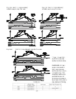
Fig. 4.4f Fn=0 direct keypad operator
control setting *see note
Fig. 4.4g Fn=1 TM2 analog input
*see note
4.4.5 Timing diagrams of speed command methods.
The following are timing diagrams explaining the various methods of speed control available at code
Fn11.
Fig. 4.4h Fn11=2 2-5 distinct preset speeds *see note


