


15
3.5
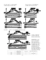
Motor Thermal Overload Relay
To prevent the motor from overheating and to adhere to UL and NEC requirements, an external
thermal relay (MOL) should be mounted between the inverter output terminals (T1, T2, T3) and the
motor. (See Fig. 3.1 and 3.2)
NOTE:
The thermal overload relay protection can be supplemented when using a motor with
thermal detectors embedded in the windings of the motor. TEFC fan cooled motors will overheat in
low speed operation. The use of thermal detectors in the motor is recommended when using TEFC
fan cooled motors. Thermal detectors will always provide a level of protection not possible with
conventional thermal overload relay.
NOTE:
The thermal overload relay should be selected to match the motor's full load current rating.
NOTE:
When multiple motors are being driven by a single inverter a separate thermal overload
relay should be provided for each motor sized to match each individual motor's full load current.
Motor thermal sensors should be wired in series.
3.6
Brake Motor Magnetic Contactor
Inverter generates a variable voltage output. For this reason, when using a brake motor with in-
verter, the brake power supply must be connected directly to the AC line power through a suitable
brake contactor (re: 100A09ND3)...DO NOT connect to inverter output. This branch circuit should
be fused in accordance with NEC regulations. The coil of the brake contactor should be connected
to the running relay output provided on the D61530 at terminals RLA, RLB, RLC. See page 11 and
12 or specific wiring diagrams.
NOTE:
A suitable surge absorber is strongly recommended to be installed on line side of the brake
contactor to prevent transient voltage surge when the brake contactor is de-energized the brake
contactor coil should also be suppressed.
For single or three phase AC coil brakes, please use R-C supressor such as Drivecon number
KVFCC-3.
For DC coil brakes, please use diode type supressor.
See page 13 for connection details.
3.7
Special Cautions on Wiring
CAUTION:
DO NOT connect AC power source to inverter output terminal (T1, T2, T3). This will
seriously damage the unit.
CAUTION:
DO NOT install magnetic contactor (MC) between the inverter output terminal and
motor. Closing of such unit while inverter is in run mode will result in large transient current to
damage the unit or lead inverter to trip. Consult Drivecon if such a contactor is required.
CAUTION:
DO NOT install power factor correction capacitor between inverter output terminal
(T1, T2, T3) and motor.
CAUTION:
DO NOT megger the motor leads while inverter is connected to motor. The semicon-
ductor output module (TRM) will be destroyed by high test voltage.
CAUTION:
Source KVA must be limited to < 500 KVA to protect against premature rectifier
assembly


