background image

Operation & Maintenance Manual  Section4-Machine Controls and Indicators 


Dingli Machinery 


4-13 


Enter

ACT

a

r

h

l

STOP

Index

+

-


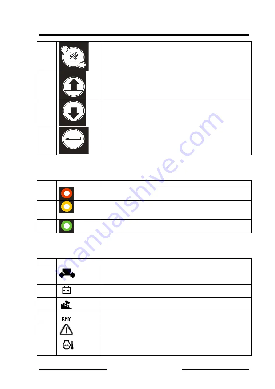
It is used to adjust the display panel contrast, press one time 

Enter

ACT

a

r

h

l

STOP

Index

+

-


Go  back  to  up  class  menu  or  display  item.  It  is  used  to  choose 
previews item when adjust the display menu 

Enter

ACT

a

r

h

l

STOP

Index

+

-


Go down to the next display item. It is used to choose next item 
when adjust the display menu 

Enter

ACT

a

r

h

l

STOP

Index

+

-


It  is  used  to  confirm  you  choosing  when  make  adjusting  for  the 
control display 

 
Indicator Light Description: 
 

Item 

Name & Figure 

Description 

Enter

ACT

a

r

h

l

STOP

Index

+

-


It is a red indicator light. It indicates that there are some warnings 
when it is illustrated. 

Enter

ACT

a

r

h

l

STOP

Index

+

-


It is a yellow indicator light. It indicates that the driving motor is 
in  minor  display  and  the  machine  can  be  drove  in  High  speed 
when it is illustrated. 

Enter

ACT

a

r

h

l

STOP

Index

+

-


It  is  a  green  indicator  light.  It  indicates  that  the  footswitch  is 
depressed when it is illustrated. 

 
The Icon in the Graphic Display Zone Description: 
 

Item 

Name & Figure 

Description 


The ground control station indicator. It would be shown when the 
selected key switch is turned to the ground control station. 


Indicate that the engine is turn off. 


Indicate  that  the  machine  chassis  is  inline  and  the  degree  more 
that 3 degree. 


Indicate that the engine is in High speed working status. 


Indicate that the emergency button is depressed down. 


Indicate  that  the  engine  coolant  temperature  is  more105  degree. 
Stop the engine immaterially and make a troubleshooting.   

Summary of Contents for BA14J-AWD

Page 1: ...Operation Maintenance Manual Table of Contents Dingli Machinery i Series 1 ...

Page 2: ...pping Hazards 1 6 Crushing and Collision Hazards 1 8 1 5 Towing Lifting and Hauling 1 9 1 6 Additional Hazards Safety 1 9 Section 2 Specifications 2 1 2 1 Machine Specifications 2 1 2 2 Performance Specifications 2 2 2 3 Hydraulic Specifications 2 4 2 4 Kubota 2403 M Engine Specifications 2 5 2 5 Perkins 404D 22 Engine Specifications 2 6 2 6 Bolt Torque Specifications 2 6 Section 3 User responsibi...

Page 3: ...rol Indicator Panel 4 2 4 2 2 Platform Control Station 4 6 4 2 3 The Multi Function Gauge 4 11 4 2 4 The Control Unit Display Panel 4 12 4 3 Tilt Alarm Warning 4 14 4 4 Footswitch Enable Indicator 4 14 4 5 Placards and Decals 4 15 Section 5 Operation Instruction 5 1 5 1 Description 5 1 5 2 Operating Characteristics and Limitations 5 2 Capacities 5 2 Stability 5 2 5 3 Engine Operation 5 5 Staring P...

Page 4: ... 5 10 5 12 Lifting and Tie Down 5 10 Lifting Operation 5 10 Tie Down Operation 5 10 5 13 Towing Operation 5 14 Prior to Towing 5 14 Section 6 Emergency Procedures 6 1 6 1 General 6 1 6 2 Emergency Towing Procedures 6 2 6 3 Emergency Controls and Their Locations 6 2 Power Emergency Stop Switches 6 2 Ground Control Station 6 2 Auxiliary Power 6 2 6 4 Emergency Operation 6 3 Use of Ground Controls 6 ...

Page 5: ...er Procedure 7 5 Replace the Return Filter Procedure 7 6 Replace the Suction Filter Procedure 7 7 7 4 5 Replace the Engine Oil 7 7 7 4 6 Replace the Engine Fuel Filter 7 7 7 4 7 Replace the Water Separator 7 8 7 4 8 Tires Wheels Maintenance 7 9 Tire Damage 7 9 Tire Replacement 7 9 Wheel Replacement 7 9 Wheel Installation 7 9 7 4 9 Battery Maintenance 7 10 Section 8 Troubleshooting and Schematics 8...

Page 6: ...nsure that the product will not be damaged or be made unsafe by the operation lubrication maintenance or repair procedure that you choose 4 The information specifications and illustrations in this publication are on the basis of information that was available at the time that the publication was written Due to the continuous improvements Dingli reserve the rights to make the specifications changes...

Page 7: ...air are caused by failure to observe basic safety rules or precautions An accident can often be avoided by recognizing potentially hazardous situations before an accident occurs A person must be alerted to potential hazards This person should also have the necessary training skills and tools to perform these functions properly Improper operation lubrication maintenance or repair of this product ca...

Page 8: ...Precaution FAILURE TO COMPLY WITH THE SAFETY PRECAUTIONS LISTED IN THIS MANUAL COULD RESULT IN MACHINE DAMAGE PROPERTY DAMAGE PERSONAL INJURY OR DEATH Operator Training and Knowledge Read and understand this manual before operating the machine Read understand and obey all DANGERS WARNINGS CAUTIONS and operating instructions on the machine and in this manual Do not operate this machine until comple...

Page 9: ...this machine until it has been serviced and maintained according to requirements specified by the manufacture Be sure the footswitch and all other safety devices are operating properly Modification of these devices is a safety violation MODIFICATION OR ALTERATION OF AN AERIAL WORK PLATFORM SHALL BE MADE ONLY WITH WRITTEN PERMISSION FROM THE MANUFACTURER Do not operate any machine on which safety o...

Page 10: ...ols which extend outside the platform are prohibited unless approved When driving always position boom over rear axle in line with the direction of travel Remember if boom is over the front axle steer and drive functions will be reversed Do not assist a stuck or disabled machine by pushing pulling or by using boom functions Only pull the unit from the tie down lugs on the chassis Do not place boom...

Page 11: ...leave the platform Use extreme caution when entering or leaving platform Be sure that the boom is fully lowered It may be necessary to telescope out to position the platform closer to the ground for entry exit Face the machine maintain three point contact with the machine using two hands and one foot or two feet and one hand during entry and exit Electrocution Hazards This machine is not insulated...

Page 12: ...apparatus carrying up to 50 000 volts One foot additional clearance is required for every additional 30 000 volts or less The minimum approach distance may be reduced if insulating barriers are installed to prevent contact and the barriers are rated for the voltage of the line being guarded These barriers shall not be part of or attached to the machine The minimum approach distance shall be reduce...

Page 13: ... the platform or drive from an elevated position unless the machine is on firm level and smooth surfaces Keep the chassis of the machine at least 2 ft 0 6m from holes bumps drop offs obstructions debris concealed holes and other potential hazards on the floor surface Do not push or pull any object with the boom Never attempt to use the machine as a crane Do not tie off machine to any adjacent stru...

Page 14: ...form when lifting or lowering platform and driving During operation keep all body parts inside platform railing Use the boom functions not the drive function to position the platform close to obstacles Always post a lookout when driving in areas where vision is obstructed Keep non operating personnel at least 6 ft 1 8m away from machine during all driving and swing operations Limit travel speed ac...

Page 15: ...ecessary 1 5 TOWING LIFTING AND HAULING Never allow personnel in platform while towing lifting or hauling This machine should not be towed except in the event of emergency malfunction power failure or loading unloading Refer to the Emergency Procedures section of this manual for emergency towing procedures Ensure boom is in the stowed position and the turntable locked prior to towing lifting or ha...

Page 16: ...rforming welding or metal cutting operations precautions must be taken to protect the chassis from direct exposure to weld and metal cutting spatter Do not refuel the machine with the engine running Battery fluid is highly corrosive Avoid contact with skin and clothing at all times Charge batteries only in a well ventilated area ...

Page 17: ... 7500kg Ground Clearance 0 30m Operation Dimension Maximum Platform Height 14m Maximum Platform Working Height 16m Maximum Up and Over Height 7 67m Maximum Horizontal Reach 7 47 Main Boom Up Angle 75 Main Boom Down Angle 24 Maximum Turntable Tailswing 0 Wheelbase 2 2m Minimum Turning Circle Inside 2 22m Maximum Turning Circle Outside 5 10m Turntable Rotation 357 non continuous Platform Rotation 16...

Page 18: ...e 12 16 5 Outer Diameter 818mm Width 305 Weight 227 kg 2 2 Performance Specification Driving Speed Boom Stowed high range 6km h Boom Raised or Extended 1 1km h Gradeability Stowed 40 for 4 4 drive 30 for 4 2 drive Main Lift Up 24 28 sec Main Lift Down 20 24 sec Swing Right Left 80 90 sec Telescope Extent Out 15 20 sec Telescope Retract In 9 15 sec Platform Rotate R L 25 32 sec Jib Up 20 31 sec Jib...

Page 19: ... surface Drive Select Switch should be set to 2WD High Engine The Platform Speed Knob should be selected out of the creep speed This verifies that the switches are working when the boom is above horizontal Results should be recorded for a 50 ft course Drive Forward Record Time Drive Reverse Record Time Platform Rotate Platform level and completely rotated one direction Rotate the opposite directio...

Page 20: ...Motor Rated Working Pressure 340 bar Function Pump Type Gear Pump Rated Working Pressure 250 bar Displacement per revolution 14cc Hydraulic Tank Return Filter 10um Dive Manifold Motor Shift Brake Release Pressure 20 bar 4WD Front Motor Flow Regulation 4WD Rear Motor Flow Regulation 2WD Rear Motor Flow Regulation Function Manifold Function Main Relief Pressure used for Lower Mid Boom Up and Down Ma...

Page 21: ... 2 Low Idle 1200 rpm High Idle Less than 2645 rpm Governor Centrifugal ball mechanical Compression Ratio 20 5 Valve Clearance cold 0 2mm Intake 2 45 250 kPa mmAq Exhaust 7 64 m3 min Lubrication System Forced Lubricating by Trochoid Pump Oil Pressure 0 5kgf cm2 Oil Capacity 9 5L Oil Viscosity Requirements Better than API CD class 10W 30 Use Oil Meeting API Classification SF labeled SF CC or SF CD f...

Page 22: ...ystem Oil Pressure hot at 2000rpm 2 8 to 4 1 bar Oil Capacity Including Filter 8 9 t0 10 6 liters Oil Viscosity Requirement Unit ships with 15 W40 oil Extreme operating temperatures may require the use of alternative engine oils Please refer the Engine Operator Manual for detail information Battery Type 12V 95Ah Quality 1 Fuel Requirement Please refer to the engine Operator s Manual on your machin...

Page 23: ... 18 M8 25 36 43 M8 1 27 39 46 M10 49 72 84 M10 1 52 76 90 M12 1 25 93 135 160 M12 1 5 89 130 155 M12 86 126 145 M14 1 5 145 215 255 M14 135 200 236 M16 1 5 226 330 390 M16 210 310 365 M18 1 5 340 485 570 M18 300 430 600 M20 1 5 475 680 790 M20 425 610 710 M22 1 5 630 900 1050 M22 580 820 960 M24 2 800 1150 1350 M24 730 1050 1220 M27 2 1150 1650 1950 M27 1100 1550 1800 M30 2 1650 2350 2750 M30 1450...

Page 24: ...t means to operate the machine where overhead obstructions other moving equipment and obstacles depressions holes drop offs Means to avoid the hazards of unprotected electrical conductors Specific job requirements or machine application Training Supervision Training must be done under the supervision of a qualified person in an open area free of obstructions until the trainee has developed the abi...

Page 25: ...se or rental delivery Owner Dealer or User Operation and Maintenance Manual and applicable Dingli Inspection Form Frequent Inspection In service for 3 months or 150 hours whichever comes first or Out of service for a period of more than 3 months or Purchased used Owner Dealer or User Operation and Maintenance Manual and applicable Dingli Inspection Form Annual Machine Inspection Annually no later ...

Page 26: ...f usage This inspection checklist is also applicable and must be followed for all machines that have been in storage or for all machines that will be exposed to harsh or changing climates These checks are also to be performed after maintenance has been performed on the machine Chassis 1 Check front tires and wheel assemblies for loose or worn spindles components and hardware for security tires for...

Page 27: ...3 Check all electrical cables for defects damage loose or corroded connections Boom 1 Check Lower Boom and leveling link for damage missing parts and security 2 Check all pin and shaft retaining hardware for security and wear 3 Check hydraulic lines and electrical cable for damage missing parts and security 4 Check limits switch connections and plunger for corrosion and security 5 Check Lower Upri...

Page 28: ... an aid to the operator in the event he she notices a condition that requires prompt attention during the walk around inspection or during operation until the proper service personnel can be notified The Service and Maintenance manual provides specific torque values and periodic maintenance procedures with a listing of individual components Utilizing this Torque Value Table in conjunction with the...

Page 29: ...ION NOTE Check boom limit switches on upright for proper operation and security both visually and manually The lower switch cuts out drive speed when the lower boom is above horizontal The upper switch cuts out drive speed when the upper boom is above horizontal Only creep drive speed will continue to function 6 Check platform footswitch for proper operation Switch must be released to start engine...

Page 30: ...ce Manual Section3 User Responsibility Machine Preparation and Inspection Dingli Machinery 3 7 1 2 4 3 5 6 8 7 9 10 11 15 12 13 14 16 17 18 19 20 21 23 24 22 25 28 26 27 29 Figure 3 1 Daily Walk around Inspection Position ...

Page 31: ...9 Hood Right Side Properly secured no loose or missing parts 10 Ground Controls Switches operable no visible damage decals secure and legible 11 Fuel Supply Filler cap secure no visible damage to the tank or evidence of leaks 12 Tie Rod Ends and Steering Spindles No loose or missing parts no visible damage 13 Drive Motor Brake and Hub No visible damage no evidence of leakage 14 Oscillating Axle No...

Page 32: ...obstructions First using the ground controls check all functions controlled by the ground controls Next using the platform controls check all functions controlled by the platform controls TO AVOID SERIOUS INJURY DO NOT OPERATE MACHINE IF ANY CONTROL LEVERS OR TOGGLE SWITCHES CONTROLLING PLATFORM MOVEMENTS DO NOT RETURN TO THE OFF OR NEUTRAL POSITION WHEN RELEASED TO AVOID A COLLISION AND INJURY IF...

Page 33: ...BE ADJUSTED SO THAT FUNCTIONS WILL OPERATE WHEN PEDAL IS APPROXIMATELY AT ITS CENTER OF TRAVEL IF SWITCH OPERATES WITHIN LAST 1 4 OF TRAVEL TOP OR BOTTOM IT SHOULD BE ADJUSTED A Activate hydraulic system by depressing footswitch Operate Telescope and hold control Remove foot from footswitch motion should stop If it does not shut down machine and contact a certified service technician B With footsw...

Page 34: ...oom to stowed position centered between drive wheels When boom reaches center stowed position lockout cylinders should release and allow wheel to rest on ground it may be necessary to activate Drive to release cylinders 8 Place the 8 inches 20 cm high block with ascension ramp in front of right front wheel 9 Place Drive control lever to Forward and carefully drive machine up ascension ramp until r...

Page 35: ... provides the necessary information needed to understand control functions 4 2Controls and Indicators 4 2 1 Ground Control Station NOTE If equipped the Function Enable switch must be held down in order to operate Telescope Swing Tower Lift Main Lift Jib Lift Platform Level Override and Platform Rotate functions DO NOT OPERATE FROM GROUND CONTROL STATION WITH PERSONNEL IN THE PLATFORM EXCEPT IN AN ...

Page 36: ...Operation Maintenance Manual Section4 Machine Controls and Indicators Dingli Machinery 4 2 1 3 5 7 4 6 2 8 9 10 12 11 ...

Page 37: ...h the Toggle Switch to Rabbit direction two times the engine would be turning in low speed once a function action is chosen the engine would be turning in Lower or High speed against the speed set by the system 3 The Ground and Platform Console Selecting Switch A three position toggle switch is used to supplies power to the platform console or platform console when positioned to Platform Normally ...

Page 38: ...rol Switch A three position Toggle Switch allows the operator to swing the turntable to left or right according the indication direction 6 Emergency Button A two position red mushroom shaped switch furnishes power to Ground Select switch when pull out ON When pushed in OFF power is shut off to the Ground Select switch 7 The Control Switch for Lower and Mid Boom Up Down A Three Position Toggle Swit...

Page 39: ...ing and lowering of the Main Boom 9 The Main Boom Telescopic Controller Three Position Toggle Switch Provides for extension and retraction of the Main Boom 10 The Jib Boom Up Down Controller Three Position Toggle Switch Provides for Raiding and Lowering of the Jib Boom 11 The Platform Rotate Controller A three position Toggle Switch allows the operator to rotate the Platform ...

Page 40: ...adjust the automatic self leveling system This switch is used to adjust the platform level in situations such as ascending descending a grad ONLY USE THE PLATFORM LEVELING OVERRIDE FUNCTION FOR SLIGHT LEVELING OF THE PLATFORM INCORRECT USE COULD CAUSE THE LOAD OCCUPANTS TO SHIFT OR FALL FAILURE TO DO SO COULD RESULT IN DEATH OR SERIOUS INJURY 4 2 2 Platform Control Station ...

Page 41: ...Operation Maintenance Manual Section4 Machine Controls and Indicators Dingli Machinery 4 7 Figure 4 2 Platform Console Panel 11 10 9 8 7 6 5 4 3 2 1 17 16 15 14 13 12 ...

Page 42: ...used for assisting method to start the engine when the temperature is lower Push Forward and Hold it about 8 Second then release the toggle lever to Push the Start Toggle Switch to Start the engine 3 The Engine Start Switch A Toggle Switch Push Up Forward until the engine starts it would return Back to Original Position Automatically once be released Note It only be function after the Selecting Sw...

Page 43: ...Two Position Toggle Switch which is used to set the engine speed there are three working model The engine speed is set at Low speed default after the engine is started Push the Toggle Switch to Rabbit direction one time the engine would be turning in highest speed no matter a function action is chosen or not Push the Toggle Switch to Rabbit direction two times the engine would be turning in low sp...

Page 44: ...tform Leveling Control Switch A three position switch allows the operator to adjust the automatic self leveling system This switch is used to adjust the platform level in situations such as ascending descending a grade ONLY USE THE PLATFORM LEVELING OVERRIDE FUNCTION FOR SLIGHT LEVELING OF THE PLATFORM INCORRECT USE COULD CAUSE THE LOAD OCCUPANTS TO SHIFT OR FALL FAILURE TO DO SO COULD RESULT IN D...

Page 45: ... Controls and Indicators Dingli Machinery 4 11 of the joystick 4 2 3 The Multi Function Gauge Item Name Figure Description 1 Hydraulic Filter Warning indicator It would be displayed once the filter is clogged Change the filter element immediately ...

Page 46: ...d once the coolant temperature is higher more that 105 Stop the machine immediately to cool the hydraulic oil and make a troubleshooting 4 Engine Oil Presser Warning Indicator it would be display once the engine oil pressure is too low Stop the machine immediately to make a troubleshooting 5 Indicate that the engine is turn off 6 System Error Warning indicator 7 Low Charge Pressure Warning Indicat...

Page 47: ...re some warnings when it is illustrated 2 Enter A C T a r h l S TO P Index It is a yellow indicator light It indicates that the driving motor is in minor display and the machine can be drove in High speed when it is illustrated 3 Enter AC T a r h l S TO P Index It is a green indicator light It indicates that the footswitch is depressed when it is illustrated The Icon in the Graphic Display Zone De...

Page 48: ...t it is level before continuing operation If the boom is above horizontal and the machine is on a slope the tilt alarm will sound and the Main Boom Raising and Extending would be not function TILT WARNING LIGHT IS ILLUMINATED WHEN BOOM IS RAISED OR EXTENDED RETRACT AND LOWER TO BELOW HORIZONTAL THEN REPOSITION MACHINE SO THAT IT IS LEVEL BEFORE EXTENDING BOOM OR RAISING BOOM ABOVE HORIZONTAL 4 4Fo...

Page 49: ...R WARNING CAUTION OR INSTRUCTION PLACARDS OR DECALS ARE MISSING OR ILLEGIBLE Replace placards and decals if damaged missing or illegible Decals are made of Pressure Sensitive Adhesive with a protective film on the front Remove the damaged decal and thoroughly clean surface before installing a new decal Simply peel off the back and press new decal onto surface NOTE Placards and Decals can be ordere...

Page 50: ...Operation Maintenance Manual Section4 Machine Controls and Indicators Dingli Machinery 4 16 Figure 4 5 Danger and Warning Decal Position ...

Page 51: ...Operation Maintenance Manual Section4 Machine Controls and Indicators Dingli Machinery 4 17 ...

Page 52: ...Operation Maintenance Manual Section4 Machine Controls and Indicators Dingli Machinery 4 18 ...

Page 53: ...Operation Maintenance Manual Section4 Machine Controls and Indicators Dingli Machinery 4 19 ...

Page 54: ...resh in their minds The machine is designed to provide efficient and safe operation when maintained and operated in accordance with warnings on the machine in the Operation Maintenance Manual and all jobsite and government rules and regulations As with any type of machinery the operator is very important to efficient and safe operation It is absolutely necessary that the machine be regularly maint...

Page 55: ...to the neutral position The unrestricted capacity of the machine is 230 kg This means that with a platform load of 230 kg or less the platform may be positioned anywhere the boom will reach 5 2Operating Characteristics and Limitations Capacities The boom can be raised above horizontal with or without any load in platform if 1 Machine is positioned on a smooth firm and level surface 2 Load is withi...

Page 56: ...nstruction Dingli Machinery 5 3 M ACHINE WILL TIP OVER IN THIS DIRECTION IF OVERLOADED OR OPERATED ON AN OUT OF LEVEL SURFACE TELESCOPE FULLY EXTENDED UPPER BOOM HORIZONTAL LOWER MID BOOM STOWED POSITION Figure 5 1 Position of Least Forward Stability ...

Page 57: ...chinery 5 4 Figure 5 2 Position of Least Backward Stability ROTATE THE PLATFORM 90 DEGREES MACHINE WILL TIP OVER IN THIS DIRECTION IF OPERATED ON AN OUT OF LEVER SURFACE MAIN BOOM FULLY RAISED AND THE PLYBOOM FULLY RETRACTED MID BOOM FULLY RAISED LOWER BOOM FULLY RAISED ...

Page 58: ...until engine starts ALLOW ENGINE TO WARM UP FOR A FEW MINUTES AT LOW SPEED BEFORE APPLYING ANY LOAD 2 After engine has had sufficient time to warm up shut engine off 3 Turn SELECT switch to PLATFORM 4 From Platform pull POWER EMERGENCY STOP switch out then push the ENGINE START switch until engine starts NOTE Footswitch must be in released up position before starter will operate If starter operate...

Page 59: ... AT ALL TIMES WHEN THE PLATFORM IS ELEVATED TRAVEL GRADES WITH DRIVE SPEED TORQUE SELECT SWITCH IN THE FORWARD POSITION USE CAUTION WHEN DRIVING IN REVERSE AND WHEN DRIVING WITH PLATFORM ELEVATED ESPECIALLY WHEN DRIVING WITH ANY PART OF MACHINE WITHIN 6 FEET 2 M OF AN OBSTRUCTION BEFORE DRIVING MAKE SURE BOOM IS POSITIONED OVER REAR DRIVE AXLE IF BOOM IS OVER FRONT WHEELS STEER AND DRIVE CONTROLS ...

Page 60: ... Switch Level to Up and hold until platform is level 2 Leveling Down Activated the FootSwitch to Raise platform Position the Platform Level Toggle Switch Level to Down and hold until the platform is level Platform Rotation 1 Activated the FootSwitch 2 To rotate the platform to the left or right use the Platform Rotate control switch to select the direction and hold until desired position is reache...

Page 61: ...operation Check Boom Upright tilting for proper synchronization If the upright is tilted or the boom will not fully lower Adjustment should be done according to the Boom Synchronizing Procedure below Boom Synchronizing Procedure If the lower boom does not fully lower use the following procedure 1 Remove all personnel from the platform 2 Pull out the red EMS emergency stop knob located on the groun...

Page 62: ...Auxiliary Pump Operation WHEN OPERATING ON AUXILIARY POWER DO NOT OPERATE MORE THAN ONE FUNCTION AT THE SAME TIME SIMULTANEOUS OPERATION CAN OVERLOAD THE AUXILIARY PUMP MOTOR The main function of auxiliary power is to lower the platform in the event of primary power failure Determine the reason for primary power failure and have the problem corrected by a certified service technician Operate as fo...

Page 63: ...le to protect instruction placards warning decals and operating controls from hostile environment 5 12 LIFTING AND TIE DOWN Lifting 1 Refer to the Serial Number Tag to make sure the Gross Vehicle Weight 2 Place the boom in the stowed position 3 Remove all loose items from the machine 4 Properly adjust the rigging to prevent damage to the machine and so the machine remains level If it becomes neces...

Page 64: ...Manual Section5 Operation Instruction Dingli Machinery 5 11 1 Place the boom in the stowed position 2 Remove all loose items from the machine 3 Secure the chassis and the platform using straps or chains of adequate strength ...

Page 65: ...Operation Maintenance Manual Section5 Operation Instruction Dingli Machinery 5 12 Lift Here Lift Here Figure 5 3 Lifting Diagram ...

Page 66: ...Operation Maintenance Manual Section5 Operation Instruction Dingli Machinery 5 13 Figure 5 4 Tie Down Diagram ...

Page 67: ...XIMUM TOWING SPEED 5 M P H 8 K M H FOR NO LONGER THAN 30 45 MINUTES MAXIMUM TOWING GRADE 25 Prior to Towing Prior to towing the machine complete the following DO NOT TOW MACHINE WITH ENGINE OPERATING OR DRIVE HUBS ENGAGED 1 Retract lower and position boom over rear drive wheels in line with direction of travel 2 Disconnect drive hubs by inverting disconnect cap See Figure 5 5 After towing the mach...

Page 68: ... include any work or contact with the machine 6 2 Emergency Towing Procedures Towing this machine is prohibited unless properly equipped However provisions for moving the machine in case of a malfunction or power failure have been incorporated The following procedures are to be used ONLY for emergency movement to a suitable maintenance area 1 Chock wheels securely 2 Disengage drive hubs by reversi...

Page 69: ... from the ground Place the KEY SELECT switch to GROUND position and operate the proper switch to lift swing or telescope the boom or level the platform Auxiliary Power A toggle type auxiliary power control switch is located on the platform control station and another is located on the ground control station Operation of either switch turns on the electrically driven auxiliary hydraulic pump This s...

Page 70: ...review and understanding of this section and hands on operation of the controls in simulated emergencies Operator Unable to Control Machine If the Platform Operator Is Pined Trapped or Unable to Operate or Control the Machine DO NOT OPERATE WITH PRIMARY POWER SOURCE ENGINE OR ELECTRIC MOTOR IF PERSONS ARE PINNED OR TRAPPED USE AUXILIARY POWER INSTEAD 1 Operate the machine from ground controls ONLY...

Page 71: ... are operating correctly A cold weather start system in the diesel engine functions automatically to provide starting fluid as necessary to the engine A sensor switch mounted on the engine will permit ether injection when the engine is cold The sensor will not permit ether injection to a warm engine 6 5 Incident Notification It is imperative that Dingli Machinery Co Ltd be notified immediately of ...

Page 72: ...rease having a minimum dripping point of 350 F 177 C Excellent water resistance and adhesive qualities and being of extreme pressure type Timken OK 40 pounds minimum EPGL Extreme Pressure Gear Lube oil meeting API service classifica tion GL 5 or MIL Spec MIL L 2105 HO Hydraulic Oil API service classification GL 3 e g Mobilfluid 424 EO Engine crankcase Oil Gas API SF SH SG class MIL L 2104 Diesel A...

Page 73: ...Operation Maintenance Manual Section7 General Maintenance Dingli Machinery 7 2 4 2 3 1 5 8 6 7 Configer7 1 Operator Maintenance and Lubrication Diagram ...

Page 74: ... Drive the machine until one plug is at the top and the other is at 90 degree d Fill the hub with oil from the top hole until the oil level is even with the bottom of the side hole e Apply pipe thread sealant to the plugs then to install the plugs f Repeat this procedure for each torque hub 7 4 2 Lubrication for the Swing Bearing and Worm Gear Yearly application to lubrication to the turntable bea...

Page 75: ...Remove grease fittings and install plugs after greasing 7 4 3 Test and Replace the Hydraulic Oil Replacement and testing of the hydraulic oil is essential for good machine performance and service life Dirty oil and suction strainers may cause the machine poorly and continued use may cause components damage Extremely dirty conditions may require oil changes to be performed more often THE MACHINE US...

Page 76: ...e synchronizing valve and disconnect the end fitting which is located on the hydraulic reservoir and block the port in the reservoir Then take a suitable container under the hose to accept the oil 17 Start the engine in the Ground Control Station put the toggle switch lever forward to raise the Lower Boom take the hose and let the oil from the cylinder non rid chamber into the container 18 Stop th...

Page 77: ...re 1 Clean the area around the oil filter then remove the filter assembly cover use a 3mm wrench 2 pull out the filter element from the filter assembly chamber 3 Install the new filter element to the filter assembly chamber 4 Install the filter assembly cover and tighten it Clean up any oil that may have spilled during the replacement procedure 5 The charge filter assembly Dingli Part Number is RF...

Page 78: ...ose adaptor to the fitting with correct torque Clean up any oil that may have spilled during the replacement procedure 6 Repeat step 1 to step 5 with another circuit suction port II the new filter element to the filter assembly chamber 7 The suction filter element Dingli Part Number is WU 63 80 J 8 Interval Every 2years or 1200 hours of operation Remove and clean at time of hydraulic oil change 7 ...

Page 79: ...R OVER FILL THE TANK OR SPILL FUEL IF FUEL IS SPILLED CLEAN IT UP IMMEDIATELY BE SURE TO USE THE CORRECT TYPE AND GRADE OF FUEL GROUND THE FUEL FUNNEL OR NOZZLE AGAINST THE FILTER NECK TO PREVENT SPARKS AND BE SURE TO REPLACE THE FUEL TANK CAP 7 4 7 Replace the Water Separator A Water Separator is installed between the Fuel tank and the Fuel filter to separate the water from the fuel It is useful ...

Page 80: ...ent tire we recommend that replacement tires have the following characteristics Equal or greater ply load rating and size of original Tire tread contact width equal or greater than original Wheel diameter width and offset dimensions equal to the original Approved for the application by the tire manufacturer including inflation pressure and maximum tire load Unless specifically approved by the manu...

Page 81: ...ross threading NOT use a lubricant on threads or nuts 2 Tighten nuts in the following sequence 3 The tightening of the nuts should be done in stages Following the recommended sequence tighten nuts per wheel torque chart TORQUE SEQUENCE 1st Stage 2nd Stage 3rd Stage 40 ft lbs 100 ft lbs 170 ft lbs 55 Nm 130 Nm 255 Nm 4 Wheel nuts should be torqued after first 50 hours of operation and after each wh...

Page 82: ...d batteries contain sulfuric acid which will damage eyes or skin on contact When working around batteries always wear a face shield to avoid acid in eyes If acid contacts eyes flush immediately either clear water and get medical attention Wear rubber gloves and protective clothing to keep acid off skin If acid contacts skin wash off immediately with clean water Disconnect the battery before workin...

Page 83: ... and electrical systems The first rule of troubleshooting any circuit that is hydraulically operated and electrically controlled is to determine if the circuit is lacking hydraulic oil and electrical control power This can be ascertained by overriding the bypass valve mechanically or electrically so that oil is available to the function valve then overriding the function valve mechanically If the ...

Page 84: ...Operation Maintenance Manual Section8 Schematics Dingli Machinery 8 2 ...

Page 85: ...Operation Maintenance Manual Section8 Schematics Dingli Machinery 8 3 ...

Page 86: ...Operation Maintenance Manual Section8 Schematics Dingli Machinery 8 4 ...

Page 87: ...Operation Maintenance Manual Section8 Schematics Dingli Machinery 8 5 ...

Page 88: ...Operation Maintenance Manual Section8 Schematics Dingli Machinery 8 6 ...

Page 89: ...Operation Maintenance Manual Section8 Schematics Dingli Machinery 8 7 ...

Page 90: ...Operation Maintenance Manual Section8 Schematics Dingli Machinery 8 8 ...

Page 91: ...Operation Maintenance Manual Section8 Schematics Dingli Machinery 8 9 ...

Page 92: ...Operation Maintenance Manual Section8 Schematics Dingli Machinery 8 10 ...

Page 93: ...Operation Maintenance Manual Section8 Schematics Dingli Machinery 8 11 ...

Page 94: ...Operation Maintenance Manual Section8 Schematics Dingli Machinery 8 12 ...

Page 95: ...Operation Maintenance Manual Section8 Schematics Dingli Machinery 8 13 ...

Page 96: ...Operation Maintenance Manual Section8 Schematics Dingli Machinery 8 14 ...

Page 97: ...Operation Maintenance Manual Section8 Schematics Dingli Machinery 8 15 ...

Reviews: