PMAC-Pack
30
Getting
Started
Jogging the Motor
With these two parameters (I130 and I131) at reasonable levels, you should get good performance in
moves. Try a jog move first. Before doing the move, set up the jog speed (I122, in counts/msec)
acceleration time (I120, in milliseconds), and S-curve time (I121, in msec) to desired values (to be safe,
use low speed and long acceleration times at first). Now type
J+<CR>
-- the motor should turn in the
positive direction.
Type
J/<CR>
-- the motor should stop. If it takes a while to stop, you were falling behind during the
move; either slow down the move next time, (I122), or increase I130 to reduce the error.
J-<CR>
should
cause the motor to turn in the negative direction, and
J/<CR>
should stop it again.
J=<CR>
should
cause the motor to jog to the last pre-jog position and stop there automatically.
If you are holding position well, but cannot move the motor, you probably do not have your hardware
limits held low. Check which limits I125 is addressed to (usually
)
LIM1), then make sure those points are
held low (to AGND), and sourcing current (unscrew the wire from the terminal block and put your
ammeter in series with this circuit if you need to confirm this). If this is not right, refer to the
Encoder
Connection and Amplifier Connection
sections, above, and re-check your connections. Additionally check
that Ix06 is set to zero to disable the motor's position following abilities.
If your motor "dies" after you give it a jog command, you have probably exceeded your fatal following
error limit. If this has happened, it is either because you have asked for a move that is more than the
system can physically do (if so, reduce I122), or because you are very badly tuned (if this is the case, you
will need to increase proportional gain I130). To restore closed-loop control, issue the
J/
command.
Optimizing Jog Performance
If your jog speed seems slower than you want, you may have run into one or more of PMAC's automatic
safety limit parameters, particularly if you have a fine-resolution system. The first of these is I119, which
is the maximum permitted motor jog acceleration, expressed in counts/msec2. The default value is quite
low for most systems. You may wish to increase it several orders of magnitude for now, to get it out of
the way.
Setting Velocity Feedforward Gain
When you are jogging at constant speed, you can monitor following error and increase velocity
feedforward gain (I132) to minimize the following error. If you have a current-loop amplifier, you will
probably set I132 equal to I131 or just slightly greater.
Setting the Integral Gain
If you want to eliminate steady-state error, bring in some integral gain. Set I133 to 10,000. This should
provide weak integral action, but enough to eliminate steady-state error over a few seconds. Now try
increasing I133 some more to get quicker action. It should be safe to raise it in increments of 10,000 to
get the performance you want (quick restoration of commanded position without introducing oscillation).
If you get oscillation, reduce the integral gain until the oscillation is eliminated. If you get no effect from
adding integral gain, check the integration limit parameter I163. If this is low (100,000 or less), it will
limit what integral gain can do. If this is the problem, set this parameter to its default value by typing
I163=*<CR>
.
Power-Up Mode
For future power-up/reset cycles, you will want to set I180 so you power up in the mode you desire. If
I180 is zero, Motor #1 will power up "killed" (0V output, AENA signal false). It will not attempt to
control until a servo command is given (usually
J/
,
A
, or
<CTRL-A>
) for a non-PMAC-commutated
motor. This I-variable must be stored in non-volatile memory (with the
SAVE
command) be effective at
the next power-up/reset cycle.
Summary of Contents for PMAC Pack
Page 10: ...PMAC Pack Table of Contents vii ...
Page 11: ......
Page 16: ...PMAC Pack Overview 5 Figure 1 1 PMAC Pack Dimension ...
Page 27: ...PMAC Pack 16 Overview ...
Page 47: ...PMAC Pack 36 Getting Started ...
Page 51: ...PMAC Pack 40 Complying with European Community EMC Requirements ...
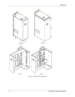
Page 53: ...PMAC Pack 42 PMACPack Custom Configuration Figure 4 1 PMAC Pack Disassembly ...
Page 70: ...PMAC Pack PMACPack Custom Configuration 59 Figure 4 4 PMAC Pack Assembly ...
Page 91: ...PMAC Pack 80 Circuit Diagrams Figure 7 2 Basic PMAC Pack Wiring Diagram ...
Page 92: ...PMAC Pack Circuit Diagrams Figure 7 3 PMAC Pack with Accessory 8D Option 2 Wiring Diagram ...
Page 93: ...PMAC Pack 82 Circuit Diagrams Figure 7 4 PMAC Pack with Accessory 8D Option 4A Wiring Diagram ...
Page 94: ...PMAC Pack Circuit Diagrams Figure 7 5 PMAC Pack with Option 9L Wiring Diagram ...
Page 95: ...PMAC Pack 84 Circuit Diagrams Figure 7 6 PMAC Pack with Accessory 28A Wiring Diagram ...
Page 96: ...PMAC Pack Circuit Diagrams Figure 7 7 PMAC Pack with Accessory 39 Wiring Diagram ...
Page 97: ...PMAC Pack 86 Circuit Diagrams ...
Page 98: ...PMAC Pack Circuit Diagrams 87 ...
Page 99: ...PMAC Pack 88 Circuit Diagrams ...
Page 100: ...PMAC Pack Circuit Diagrams 89 ...
Page 101: ...PMAC Pack 90 Circuit Diagrams ...
Page 103: ...92 Acc 24E Acc 24EXP Expansion XP Pack Figure 8 1 Expansion Pack Installation ...
Page 106: ...PMAC Pack Acc 24E Acc 24EXP Expansion XP Pack 95 Figure 8 3 PMAC Pack Assembly ...
Page 109: ...98 Acc 24E Acc 24EXP Expansion XP Pack ...


