PMAC-Pack
26
Getting
Started
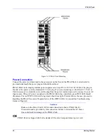
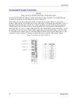
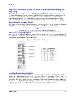
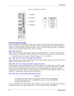
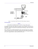
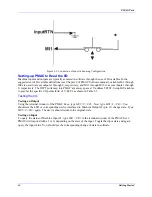
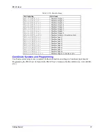
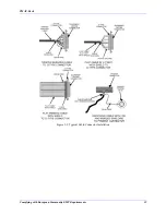
Figure 2-6. Flag Connection Pinouts
Encoder Variable Setup
Several I-variables are linked to the encoder inputs, regardless of which motor the encoder is assigned to.
These control how the encoder signal is interpreted. They are numbered in the 900s: I900-I904 belong to
Encoder 1, I905-I909 belong to Encoder 2, and so on, to I975-I979 belonging to Encoder 16. Initially we
will only concern ourselves with the first encoder’s I-variable.
I900, I905, I910, Etc.
These control the decoding of the encoder signal into counts. Quadrature x1, x2, and x4, plus pulse and
direction decode, are all possible. PMAC is shipped with counterclockwise x4 decode set up (I900, I905,
... = 7). Check this value for Encoder 1 (I900), and change it to 7 if it is different.
I901, I906, I911, Etc. Encoder Digital Filter Disable
These I-variables control whether the digital delay filter for noise spike elimination is turned on. PMAC is
shipped with the filters on (I901, I906, ... = 0).
I902, I907, I912, Etc. Encoder Position Capture Control
These I-variables control which transitions of which associated encoder signals trigger a position capture
for that encoder. This must be used for homing moves; it can also be used for other purposes. It specifies
an edge of the encoder third channel, the edge of one of the encoder flags, or the edge of a logically
combined signal from both. If it uses a flag, you must also set the next variable. The default value for this
variable is 1, specifying the rising edge of the third channel.
I903, I908, I913, Etc. Encoder Flag Select Control.
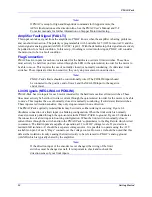
Caution:
The +LIM on the PMAC-Lite board is actually wired to the NEGLIM terminal of
the PMAC-Pack and the -LIM on the PMAC-Lite board is wired to the POSLIM
terminal of the PMAC-Pack.
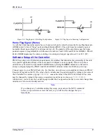
These control which of the encoder flags is used to trigger a position capture if the previous I-variable has
specified that a flag is to be used. Usually this is set to 0 to specify the home flag (HMFLn).
Summary of Contents for PMAC Pack
Page 10: ...PMAC Pack Table of Contents vii ...
Page 11: ......
Page 16: ...PMAC Pack Overview 5 Figure 1 1 PMAC Pack Dimension ...
Page 27: ...PMAC Pack 16 Overview ...
Page 47: ...PMAC Pack 36 Getting Started ...
Page 51: ...PMAC Pack 40 Complying with European Community EMC Requirements ...
Page 53: ...PMAC Pack 42 PMACPack Custom Configuration Figure 4 1 PMAC Pack Disassembly ...
Page 70: ...PMAC Pack PMACPack Custom Configuration 59 Figure 4 4 PMAC Pack Assembly ...
Page 91: ...PMAC Pack 80 Circuit Diagrams Figure 7 2 Basic PMAC Pack Wiring Diagram ...
Page 92: ...PMAC Pack Circuit Diagrams Figure 7 3 PMAC Pack with Accessory 8D Option 2 Wiring Diagram ...
Page 93: ...PMAC Pack 82 Circuit Diagrams Figure 7 4 PMAC Pack with Accessory 8D Option 4A Wiring Diagram ...
Page 94: ...PMAC Pack Circuit Diagrams Figure 7 5 PMAC Pack with Option 9L Wiring Diagram ...
Page 95: ...PMAC Pack 84 Circuit Diagrams Figure 7 6 PMAC Pack with Accessory 28A Wiring Diagram ...
Page 96: ...PMAC Pack Circuit Diagrams Figure 7 7 PMAC Pack with Accessory 39 Wiring Diagram ...
Page 97: ...PMAC Pack 86 Circuit Diagrams ...
Page 98: ...PMAC Pack Circuit Diagrams 87 ...
Page 99: ...PMAC Pack 88 Circuit Diagrams ...
Page 100: ...PMAC Pack Circuit Diagrams 89 ...
Page 101: ...PMAC Pack 90 Circuit Diagrams ...
Page 103: ...92 Acc 24E Acc 24EXP Expansion XP Pack Figure 8 1 Expansion Pack Installation ...
Page 106: ...PMAC Pack Acc 24E Acc 24EXP Expansion XP Pack 95 Figure 8 3 PMAC Pack Assembly ...
Page 109: ...98 Acc 24E Acc 24EXP Expansion XP Pack ...


