PMAC-Pack
PMACPack Mating and Connectors
67
Note:
•
All DB Connectors on the PMAC-Pack are female and all mating connectors
are female.
•
All DB connectors used must have a grounding plane and be screwed into the
PMAC-Pack when in use.
•
All cables used must be shielded with drain.
•
The shield and the drain wires must be connected at terminal point of the
connector.
•
The closest possible chassis ground terminal must be used to ground the cable.
•
All exposed wires must be kept under
5
/
8
-inch.
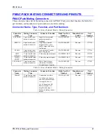
PMAC-Pack Mating Connector Pinouts
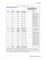
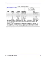
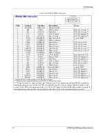
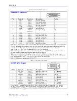
This section provides the pinouts for each of the mating connectors for PMAC-Pack ports to facilitate
customer manufacture of cables to meet individual requirements. PMAC-Pack is shipped with mating
screw terminal blocks and a power cable. Box header and DB connectors for use in making cables may be
sourced through Delta Tau, the manufacturer, or a local vendor. Delta Tau can provide pre-made cables
for many of these ports if required.
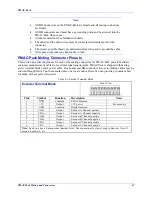
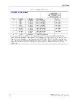
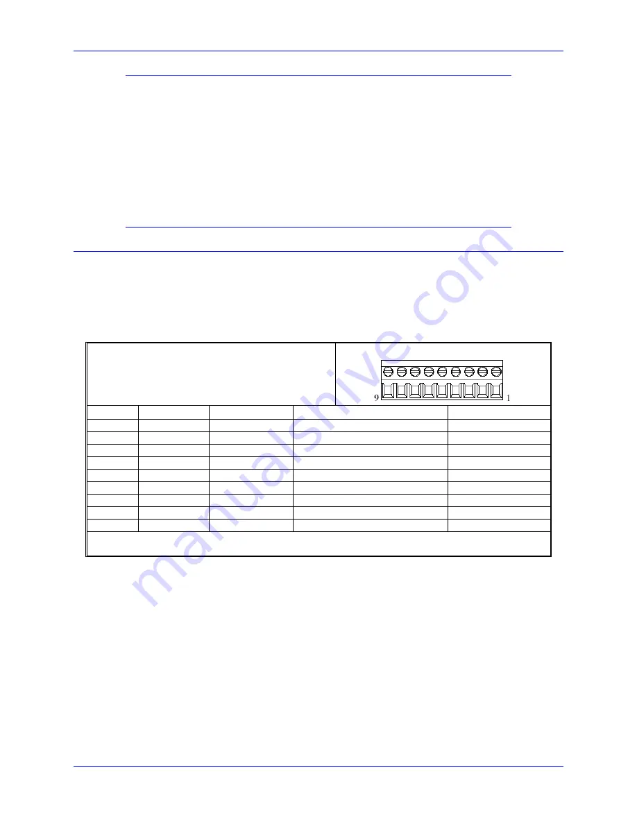
Table 6-3. Encoder Terminal Block
Encoder Terminal Block
Front View
Pin# Symbol Function
Description
Notes
1 GND Common
PMAC
common
2
+5V
Output
+5V power
For encoders
3 GND Common
Digital
common
4
CHA+
Output
Encoder A Channel positive
5
CHA-
Output
Encoder A Channel negative
6
CHB+
Output
Encoder B Channel positive
7
CHB-
Output
Encoder B Channel negative
8
CHC+
Output
Encoder C Channel positive
9
CHC-
Output
Encoder C Channel negative
Note:
Each Axis has a 9-pin encoder terminal block. The connections for Axis 1 map to Encoder 1,Axis 2
maps to Encoder 2, etc.
Summary of Contents for PMAC Pack
Page 10: ...PMAC Pack Table of Contents vii ...
Page 11: ......
Page 16: ...PMAC Pack Overview 5 Figure 1 1 PMAC Pack Dimension ...
Page 27: ...PMAC Pack 16 Overview ...
Page 47: ...PMAC Pack 36 Getting Started ...
Page 51: ...PMAC Pack 40 Complying with European Community EMC Requirements ...
Page 53: ...PMAC Pack 42 PMACPack Custom Configuration Figure 4 1 PMAC Pack Disassembly ...
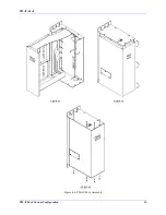
Page 70: ...PMAC Pack PMACPack Custom Configuration 59 Figure 4 4 PMAC Pack Assembly ...
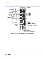
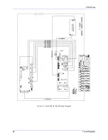
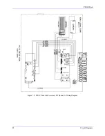
Page 91: ...PMAC Pack 80 Circuit Diagrams Figure 7 2 Basic PMAC Pack Wiring Diagram ...
Page 92: ...PMAC Pack Circuit Diagrams Figure 7 3 PMAC Pack with Accessory 8D Option 2 Wiring Diagram ...
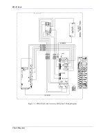
Page 93: ...PMAC Pack 82 Circuit Diagrams Figure 7 4 PMAC Pack with Accessory 8D Option 4A Wiring Diagram ...
Page 94: ...PMAC Pack Circuit Diagrams Figure 7 5 PMAC Pack with Option 9L Wiring Diagram ...
Page 95: ...PMAC Pack 84 Circuit Diagrams Figure 7 6 PMAC Pack with Accessory 28A Wiring Diagram ...
Page 96: ...PMAC Pack Circuit Diagrams Figure 7 7 PMAC Pack with Accessory 39 Wiring Diagram ...
Page 97: ...PMAC Pack 86 Circuit Diagrams ...
Page 98: ...PMAC Pack Circuit Diagrams 87 ...
Page 99: ...PMAC Pack 88 Circuit Diagrams ...
Page 100: ...PMAC Pack Circuit Diagrams 89 ...
Page 101: ...PMAC Pack 90 Circuit Diagrams ...
Page 103: ...92 Acc 24E Acc 24EXP Expansion XP Pack Figure 8 1 Expansion Pack Installation ...
Page 106: ...PMAC Pack Acc 24E Acc 24EXP Expansion XP Pack 95 Figure 8 3 PMAC Pack Assembly ...
Page 109: ...98 Acc 24E Acc 24EXP Expansion XP Pack ...

