94
Acc-24E Acc-24EXP Expansion XP Pack
PMAC-Pack/Expansion Pack Re-assembly
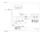
After connecting the cables inside the PMAC-Pack, perform steps 1 through 4 to reassemble the PMAC-
Pack and Expansion Pack (see Figure 8-3).
STEP #1 -
Rotate the PMAC-Lite card on its hinges until it is flush against the case standoffs. Insert the
three mounting screws to secure PMAC-Lite to the case. Check that all internal connections are secure.
STEP #2 -
Fold the left half of the PMAC-Pack casing into the right. First insert the rear lip of the left
half into the back of the case. Rotate the left half of the case until it is flush with the right. You may need
to pull the left halve slightly forward to clear the front right lip.
STEP #3 -
Insert eight sheet-metal screws as shown to secure the left and right halves of the casing
together. Leave the top and bottom screws on the right side of the PMAC-Pack loose.
STEP #4 -
Slide the PMAC-Pack and Expansion Pack together, insuring the slots in the top and bottom
brackets on the Expansion Pack slide under the PMAC-Pack screws. Any excess cable length should be
carefully inserted into the expansion Pack. Tighten the four PMAC-Pack screws.
PMAC-Pack/Expansion Pack Software Setup
The following steps will configure the PMAC-Pack software to activate and utilize Expansion Pack axes
5 through 8. These steps are necessary because the Expansion Pack adds hardware interface channels
(encoders, DACs, and flags) numbered 9 through 12, which must be mapped to motors 5 through 8.
Note:
As of February 1997, all PMAC-Packs are factory configured to use the expansion
pack. This section should be read to gain a clearer understanding of the Expansion
Pack, however, Delta Tau has preconfigured the software to control non-
commutated axes connected to the Expansion pack.
Summary of Contents for PMAC Pack
Page 10: ...PMAC Pack Table of Contents vii ...
Page 11: ......
Page 16: ...PMAC Pack Overview 5 Figure 1 1 PMAC Pack Dimension ...
Page 27: ...PMAC Pack 16 Overview ...
Page 47: ...PMAC Pack 36 Getting Started ...
Page 51: ...PMAC Pack 40 Complying with European Community EMC Requirements ...
Page 53: ...PMAC Pack 42 PMACPack Custom Configuration Figure 4 1 PMAC Pack Disassembly ...
Page 70: ...PMAC Pack PMACPack Custom Configuration 59 Figure 4 4 PMAC Pack Assembly ...
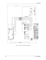
Page 91: ...PMAC Pack 80 Circuit Diagrams Figure 7 2 Basic PMAC Pack Wiring Diagram ...
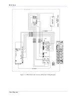
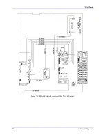
Page 92: ...PMAC Pack Circuit Diagrams Figure 7 3 PMAC Pack with Accessory 8D Option 2 Wiring Diagram ...
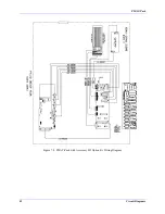
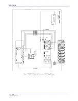
Page 93: ...PMAC Pack 82 Circuit Diagrams Figure 7 4 PMAC Pack with Accessory 8D Option 4A Wiring Diagram ...
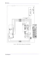
Page 94: ...PMAC Pack Circuit Diagrams Figure 7 5 PMAC Pack with Option 9L Wiring Diagram ...
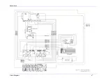
Page 95: ...PMAC Pack 84 Circuit Diagrams Figure 7 6 PMAC Pack with Accessory 28A Wiring Diagram ...
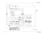
Page 96: ...PMAC Pack Circuit Diagrams Figure 7 7 PMAC Pack with Accessory 39 Wiring Diagram ...
Page 97: ...PMAC Pack 86 Circuit Diagrams ...
Page 98: ...PMAC Pack Circuit Diagrams 87 ...
Page 99: ...PMAC Pack 88 Circuit Diagrams ...
Page 100: ...PMAC Pack Circuit Diagrams 89 ...
Page 101: ...PMAC Pack 90 Circuit Diagrams ...
Page 103: ...92 Acc 24E Acc 24EXP Expansion XP Pack Figure 8 1 Expansion Pack Installation ...
Page 106: ...PMAC Pack Acc 24E Acc 24EXP Expansion XP Pack 95 Figure 8 3 PMAC Pack Assembly ...
Page 109: ...98 Acc 24E Acc 24EXP Expansion XP Pack ...

