PMAC-Pack
12 Overview
Standard PMAC-Pack
A standard PMAC-Pack provides four encoder inputs and four Digital to Analog Converter (DAC)
outputs, which may be used for control of up to four noncommutated axes or two commutated axes.
Figure 6-1, 4-Axis Non-Commutated System Interconnection Diagram, shows the connections necessary
for a typical installation. Additional options and accessories may be built into the PMAC-Pack case as
listed in Table 1-1.
Note:
Non-Commutated axes refer to axes driven motors which PMAC does not
commutate. PMAC provides a differential
)
10V torque or velocity command per
axis.
External Connections
There are many connectors on the front panel of the PMAC-Pack. Table 1-2 lists each of these connectors
and their functions.
Axis Connections
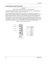
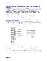
Each of the four axes on the PMAC-Pack have screw terminal connectors labeled ENCODER, SERVO,
and FLAGS.
Table 1-1. PMAC-Pack Internal Options and Accessories
Option/Accessory Number
Definition
OPT-5A
40mHz Flash-backed Memory CPU option
OPT-5B
60mHz Flash-backed Memory CPU option
OPT-6
Extended servo algorithm
OPT-9LPP
Optional RS422 Interface (required for multi-drop
communications to several PMACs on single serial
line)
ACC8D OPT-2PP
4-Channel Voltage to Frequency Converter for use with
stepper motor pulse and direction drives
ACC8D OPT-4PP
40 W 4-Channel linear amplifier for hydraulic valves
ACC8D OPT-4APP
150 W 4-Channel PWM amplifier for small DC brush
motors
ACC26APP
Serial Communications Isolator and Converter
ACC28APP
4 Channel 16 bit A/D Converter card
ACC39PP
Handwheel Encoder Interface (5th Encoder Input)
Machine Connections
In addition to the axis connections, JOPT OUTPUT, JOPT INPUT, FLT RELAY, JDISP, JPAN, JTHW,
JRS232, JRS422, and 100-240 VAC connectors are provided for machine connection.
Expansion Pack Connection
All PMAC-Pack's have a portal on the right side of the casing which allows access to a 50 pin box header
connector. This header is the JEXP header on the internally mounted PMAC-Lite card.
Accessory Connections
The TBAMP connector pertains only to PMAC-Packs configured with stepper motor V/F converters or 4
channel amplifier accessories. The JHW connector pertains only to PMAC-Packs configured with the
handwheel encoder (5th encoder channel) accessory. The JRS422 connector pertains only to PMAC-
Packs configured with the RS422 communications option. PMAC-Packs without these options retain the
connector ports, however, nothing is internally connected to them.
Summary of Contents for PMAC Pack
Page 10: ...PMAC Pack Table of Contents vii ...
Page 11: ......
Page 16: ...PMAC Pack Overview 5 Figure 1 1 PMAC Pack Dimension ...
Page 27: ...PMAC Pack 16 Overview ...
Page 47: ...PMAC Pack 36 Getting Started ...
Page 51: ...PMAC Pack 40 Complying with European Community EMC Requirements ...
Page 53: ...PMAC Pack 42 PMACPack Custom Configuration Figure 4 1 PMAC Pack Disassembly ...
Page 70: ...PMAC Pack PMACPack Custom Configuration 59 Figure 4 4 PMAC Pack Assembly ...
Page 91: ...PMAC Pack 80 Circuit Diagrams Figure 7 2 Basic PMAC Pack Wiring Diagram ...
Page 92: ...PMAC Pack Circuit Diagrams Figure 7 3 PMAC Pack with Accessory 8D Option 2 Wiring Diagram ...
Page 93: ...PMAC Pack 82 Circuit Diagrams Figure 7 4 PMAC Pack with Accessory 8D Option 4A Wiring Diagram ...
Page 94: ...PMAC Pack Circuit Diagrams Figure 7 5 PMAC Pack with Option 9L Wiring Diagram ...
Page 95: ...PMAC Pack 84 Circuit Diagrams Figure 7 6 PMAC Pack with Accessory 28A Wiring Diagram ...
Page 96: ...PMAC Pack Circuit Diagrams Figure 7 7 PMAC Pack with Accessory 39 Wiring Diagram ...
Page 97: ...PMAC Pack 86 Circuit Diagrams ...
Page 98: ...PMAC Pack Circuit Diagrams 87 ...
Page 99: ...PMAC Pack 88 Circuit Diagrams ...
Page 100: ...PMAC Pack Circuit Diagrams 89 ...
Page 101: ...PMAC Pack 90 Circuit Diagrams ...
Page 103: ...92 Acc 24E Acc 24EXP Expansion XP Pack Figure 8 1 Expansion Pack Installation ...
Page 106: ...PMAC Pack Acc 24E Acc 24EXP Expansion XP Pack 95 Figure 8 3 PMAC Pack Assembly ...
Page 109: ...98 Acc 24E Acc 24EXP Expansion XP Pack ...


