PMAC-Pack
PMACPack Custom Configuration
55
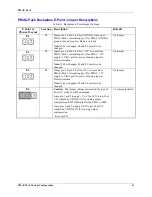
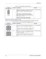
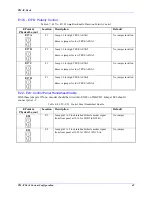
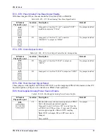
E72 - E73: Panel Analog Time Base Signal Enable
With these jumpers ON, no encoder should be wired into ENC4 on JMACH.
Table 4-20. E72 - E73: Panel Analog Time Base Signal Enable
E Point &
Physical Layout
Location Description
Default
E72
D2
Jump pin 1 to 2 to allow "V to F" converter "FOUT"
installed to output on "CHA4"
No jumper installed
E73
D2
Jump pin 1 to 2 to allow "V to F" converter
"SIGNOUT" to output on "CHB4"
No jumper installed
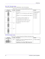
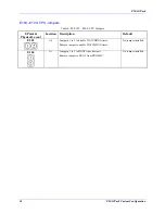
E74 - E75: Clock Output Control
Table 4-21. E74 - E75: Clock Output Control for Ext. Interpolation
E Point &
Physical Layout
Location Description
Default
E74
D2
Jump pin 1 to 2 to allow "SCLK/" to output on
"CHC4/".
No jumper installed
E75
D2
Jump pin 1 to 2 to allow "SCLK" to output on "CHC4". No jumper installed
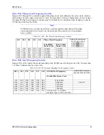
E76 - E84: Host Interrupt Signal Select
These jumpers work together with E86 and E55-E65 to set the mapping of PMAC information to host PC
bus interrupt lines. (They are of no relevance to PMAC-Pack operation.)
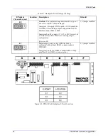
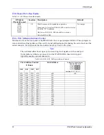
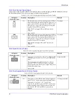
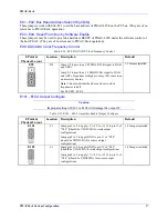
E85: Host-Supplied Analog Power Source Enable
Table 4-22. E85: Host-Supplied Analog Power Source Enable
E Point &
Physical Layout
Location Description
Default
E85
F4
E85 should be removed for normal operation of PMAC-
Pack with internal opto-isolated supplies.
Jump pin 1 to pin 2 to allow a+14V to come from bus
or PMAC-Lite's TB1 port (ties +5 logic and
)
15 analog
power supplies together. Defeats OPTO coupling.
Note:
If E85 is changed, E88 and E87 must also be
changed.
Also, see E90.
No jumper
Summary of Contents for PMAC Pack
Page 10: ...PMAC Pack Table of Contents vii ...
Page 11: ......
Page 16: ...PMAC Pack Overview 5 Figure 1 1 PMAC Pack Dimension ...
Page 27: ...PMAC Pack 16 Overview ...
Page 47: ...PMAC Pack 36 Getting Started ...
Page 51: ...PMAC Pack 40 Complying with European Community EMC Requirements ...
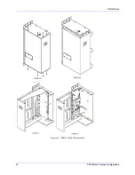
Page 53: ...PMAC Pack 42 PMACPack Custom Configuration Figure 4 1 PMAC Pack Disassembly ...
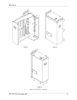
Page 70: ...PMAC Pack PMACPack Custom Configuration 59 Figure 4 4 PMAC Pack Assembly ...
Page 91: ...PMAC Pack 80 Circuit Diagrams Figure 7 2 Basic PMAC Pack Wiring Diagram ...
Page 92: ...PMAC Pack Circuit Diagrams Figure 7 3 PMAC Pack with Accessory 8D Option 2 Wiring Diagram ...
Page 93: ...PMAC Pack 82 Circuit Diagrams Figure 7 4 PMAC Pack with Accessory 8D Option 4A Wiring Diagram ...
Page 94: ...PMAC Pack Circuit Diagrams Figure 7 5 PMAC Pack with Option 9L Wiring Diagram ...
Page 95: ...PMAC Pack 84 Circuit Diagrams Figure 7 6 PMAC Pack with Accessory 28A Wiring Diagram ...
Page 96: ...PMAC Pack Circuit Diagrams Figure 7 7 PMAC Pack with Accessory 39 Wiring Diagram ...
Page 97: ...PMAC Pack 86 Circuit Diagrams ...
Page 98: ...PMAC Pack Circuit Diagrams 87 ...
Page 99: ...PMAC Pack 88 Circuit Diagrams ...
Page 100: ...PMAC Pack Circuit Diagrams 89 ...
Page 101: ...PMAC Pack 90 Circuit Diagrams ...
Page 103: ...92 Acc 24E Acc 24EXP Expansion XP Pack Figure 8 1 Expansion Pack Installation ...
Page 106: ...PMAC Pack Acc 24E Acc 24EXP Expansion XP Pack 95 Figure 8 3 PMAC Pack Assembly ...
Page 109: ...98 Acc 24E Acc 24EXP Expansion XP Pack ...

