PMAC-Pack
34
Getting
Started
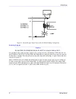
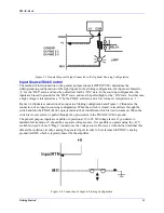
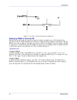
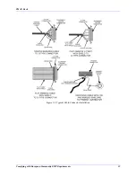
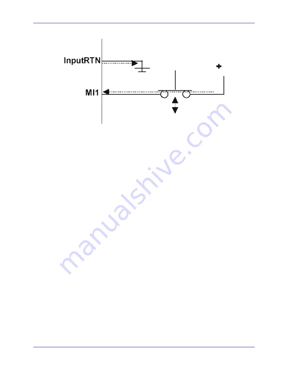
Figure 2-9. Connection of Input in Sourcing Configuration
Setting-up PMAC to Read the I/O
Machine inputs and outputs are typically accessed in software through the use of M-variables. In the
suggested set of M-variable definitions (see Chapter 9 of PMAC Software manual), variables M1 through
M8 are used to access outputs 1 through 8, respectively, and M11 through M18 to access inputs 1 through
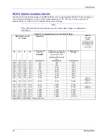
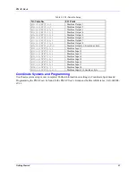
8, respectively. The JOPT ports map into PMAC's memory space at Y address $FFC2. Setup M-Variables
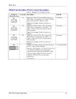
to point at the specific I/O points (bits) of Y:FFC2 as shown in Table 2-3.
Testing the I/O
Testing an Output
Using the terminal window of the PMAC Exec, type
M01=0 <CR>
. Now type
M01=1 <CR>
. You
should see the LED or corresponding device interfaced to Machine Output #1 (pin 11) change state. Type
M01=0 <CR>
again. The device should return to the original state.
Testing an Input
To query the status of Machine Input #1, type M11 <CR> in the terminal window of the PMAC Exec.
PMAC will respond with a 1 or 0, depending on the state of the input. Toggle the input state and again
query the input value. You should see the corresponding change of state in software.
Summary of Contents for PMAC Pack
Page 10: ...PMAC Pack Table of Contents vii ...
Page 11: ......
Page 16: ...PMAC Pack Overview 5 Figure 1 1 PMAC Pack Dimension ...
Page 27: ...PMAC Pack 16 Overview ...
Page 47: ...PMAC Pack 36 Getting Started ...
Page 51: ...PMAC Pack 40 Complying with European Community EMC Requirements ...
Page 53: ...PMAC Pack 42 PMACPack Custom Configuration Figure 4 1 PMAC Pack Disassembly ...
Page 70: ...PMAC Pack PMACPack Custom Configuration 59 Figure 4 4 PMAC Pack Assembly ...
Page 91: ...PMAC Pack 80 Circuit Diagrams Figure 7 2 Basic PMAC Pack Wiring Diagram ...
Page 92: ...PMAC Pack Circuit Diagrams Figure 7 3 PMAC Pack with Accessory 8D Option 2 Wiring Diagram ...
Page 93: ...PMAC Pack 82 Circuit Diagrams Figure 7 4 PMAC Pack with Accessory 8D Option 4A Wiring Diagram ...
Page 94: ...PMAC Pack Circuit Diagrams Figure 7 5 PMAC Pack with Option 9L Wiring Diagram ...
Page 95: ...PMAC Pack 84 Circuit Diagrams Figure 7 6 PMAC Pack with Accessory 28A Wiring Diagram ...
Page 96: ...PMAC Pack Circuit Diagrams Figure 7 7 PMAC Pack with Accessory 39 Wiring Diagram ...
Page 97: ...PMAC Pack 86 Circuit Diagrams ...
Page 98: ...PMAC Pack Circuit Diagrams 87 ...
Page 99: ...PMAC Pack 88 Circuit Diagrams ...
Page 100: ...PMAC Pack Circuit Diagrams 89 ...
Page 101: ...PMAC Pack 90 Circuit Diagrams ...
Page 103: ...92 Acc 24E Acc 24EXP Expansion XP Pack Figure 8 1 Expansion Pack Installation ...
Page 106: ...PMAC Pack Acc 24E Acc 24EXP Expansion XP Pack 95 Figure 8 3 PMAC Pack Assembly ...
Page 109: ...98 Acc 24E Acc 24EXP Expansion XP Pack ...

