PMAC-Pack
62
Troubleshooting
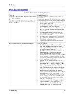
You Do Not See The Position Changing
Check the following:
•
Is the encoder receiving power (+5V and GND)?
•
Are both quadrature channels connected properly?
•
If single-ended, are the complementary lines
floating?
•
If single-ended, has E24-E27 been changed for
operation with single-ended encoders?
•
If differential, has E24-27 set for differential
encoder operation?
•
Is the motor activated (I100=1)?
•
Is I103 set to the proper encoder input?
•
Is I900 set for proper decode of the signal?
•
Can a signal be detected with a scope or voltmeter?
You Have A Polarity Mismatch
(You get a potentially dangerous runaway
condition when you try to close the loop.)
Change I900 (e.g. from 7 to 3, or 3 to 7) to reverse the
counting sense. This will change the positive direction of
the axis; if you do not wish to do this, you will need to
exchange the motor leads instead.
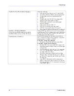
The Motor Does Not Move
Issue an O10 command to the motor which will not
move. Check the voltage on the output pin. It should be
approximately 1V relative to AGND.
If the DAC voltage HAS changed:
•
Recheck your amplifier and motor connections.
If the DAC voltage has not changed:
•
Recheck I102. You must tie the DAC output to the
motor through this variable. Check your limit-input
configuration.
•
Is your output limit (Ix69) too low? Try increasing
it to 32,767 (the maximum) to make sure PMAC
can output adequate voltage.
•
Check the analog power supply positive voltage.
Measure with a voltmeter b12V, (pin 2 of
any "FLAGS" connector) and AGND, (pin 1 of the
FLAGS port).
•
Open PMAC-Pack and check the analog power
supply voltage at the TB16 connector. You should
have approximately -12 V as measured between pin
6 and AGND (pin 5).
Summary of Contents for PMAC Pack
Page 10: ...PMAC Pack Table of Contents vii ...
Page 11: ......
Page 16: ...PMAC Pack Overview 5 Figure 1 1 PMAC Pack Dimension ...
Page 27: ...PMAC Pack 16 Overview ...
Page 47: ...PMAC Pack 36 Getting Started ...
Page 51: ...PMAC Pack 40 Complying with European Community EMC Requirements ...
Page 53: ...PMAC Pack 42 PMACPack Custom Configuration Figure 4 1 PMAC Pack Disassembly ...
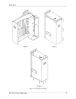
Page 70: ...PMAC Pack PMACPack Custom Configuration 59 Figure 4 4 PMAC Pack Assembly ...
Page 91: ...PMAC Pack 80 Circuit Diagrams Figure 7 2 Basic PMAC Pack Wiring Diagram ...
Page 92: ...PMAC Pack Circuit Diagrams Figure 7 3 PMAC Pack with Accessory 8D Option 2 Wiring Diagram ...
Page 93: ...PMAC Pack 82 Circuit Diagrams Figure 7 4 PMAC Pack with Accessory 8D Option 4A Wiring Diagram ...
Page 94: ...PMAC Pack Circuit Diagrams Figure 7 5 PMAC Pack with Option 9L Wiring Diagram ...
Page 95: ...PMAC Pack 84 Circuit Diagrams Figure 7 6 PMAC Pack with Accessory 28A Wiring Diagram ...
Page 96: ...PMAC Pack Circuit Diagrams Figure 7 7 PMAC Pack with Accessory 39 Wiring Diagram ...
Page 97: ...PMAC Pack 86 Circuit Diagrams ...
Page 98: ...PMAC Pack Circuit Diagrams 87 ...
Page 99: ...PMAC Pack 88 Circuit Diagrams ...
Page 100: ...PMAC Pack Circuit Diagrams 89 ...
Page 101: ...PMAC Pack 90 Circuit Diagrams ...
Page 103: ...92 Acc 24E Acc 24EXP Expansion XP Pack Figure 8 1 Expansion Pack Installation ...
Page 106: ...PMAC Pack Acc 24E Acc 24EXP Expansion XP Pack 95 Figure 8 3 PMAC Pack Assembly ...
Page 109: ...98 Acc 24E Acc 24EXP Expansion XP Pack ...

