PMAC-Pack
Complying with European Community EMC Requirements
37
COMPLYING WITH EUROPEAN COMMUNITY (CE)
EMC REQUIREMENTS
CE Compliance
If the PMAC-Pack is installed in accordance with the following instructions, it will comply with Council
Directive 89/336/EEC relating to Electromagnetic Compatibility:
•
All cables connected to the PMAC-Pack, with exception of the power supply cable, must be shielded
•
All shielded cables must be terminated at both ends
•
D-type mating connectors must have a metal shell and conform to the EMC Directive.
CE
PMAC-Pack is shipped with both standard U.S and European format power cords. The
European cord must be used to comply with electro-magnetic compatibility requirements.
Note:
Now, PMAC-Pack documentation is only available in the English language.
CE Testing and Certification
PMAC-Pack was tested and certified in accordance with the standards listed below and, if installed in
accordance with the following instructions, will comply with Council Directive 89/336/EEC relating to
electromagnetic compatibility.
EN50081-2
EN55011 Class A Group 1
EN50082-2 EN61000-4-2
ENV50140
ENV50204
EN61000-4-4
ENV50141
Cable Fabrication
There are several types of cables and connectors that can be used to install PMAC-Pack in accordance
with CE requirements. No matter which type of cables and connectors are used, the user must ensure that
each cable and connector is properly grounded in order to conform to the CE Class A emissions
requirements.
Connectors
The PMAC-Pack is supplied with all the Phoenix plug-in connectors required for installation. D-type
connectors of the appropriate size must be supplied by the customer.
Phoenix Plug-In Connectors
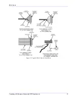
When installing the Phoenix plug-in connectors supplied with the PMAC-Pack, each individual axis
connection section has a grounding (earth) stud. The exposed portion of the cable shielding must be kept
as short as possible and terminated using a crimp-style termination ring at each connector. See Figure 3-1
for typical grounding (earthing) procedures for Phoenix plug-in connectors.
Summary of Contents for PMAC Pack
Page 10: ...PMAC Pack Table of Contents vii ...
Page 11: ......
Page 16: ...PMAC Pack Overview 5 Figure 1 1 PMAC Pack Dimension ...
Page 27: ...PMAC Pack 16 Overview ...
Page 47: ...PMAC Pack 36 Getting Started ...
Page 51: ...PMAC Pack 40 Complying with European Community EMC Requirements ...
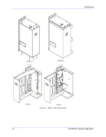
Page 53: ...PMAC Pack 42 PMACPack Custom Configuration Figure 4 1 PMAC Pack Disassembly ...
Page 70: ...PMAC Pack PMACPack Custom Configuration 59 Figure 4 4 PMAC Pack Assembly ...
Page 91: ...PMAC Pack 80 Circuit Diagrams Figure 7 2 Basic PMAC Pack Wiring Diagram ...
Page 92: ...PMAC Pack Circuit Diagrams Figure 7 3 PMAC Pack with Accessory 8D Option 2 Wiring Diagram ...
Page 93: ...PMAC Pack 82 Circuit Diagrams Figure 7 4 PMAC Pack with Accessory 8D Option 4A Wiring Diagram ...
Page 94: ...PMAC Pack Circuit Diagrams Figure 7 5 PMAC Pack with Option 9L Wiring Diagram ...
Page 95: ...PMAC Pack 84 Circuit Diagrams Figure 7 6 PMAC Pack with Accessory 28A Wiring Diagram ...
Page 96: ...PMAC Pack Circuit Diagrams Figure 7 7 PMAC Pack with Accessory 39 Wiring Diagram ...
Page 97: ...PMAC Pack 86 Circuit Diagrams ...
Page 98: ...PMAC Pack Circuit Diagrams 87 ...
Page 99: ...PMAC Pack 88 Circuit Diagrams ...
Page 100: ...PMAC Pack Circuit Diagrams 89 ...
Page 101: ...PMAC Pack 90 Circuit Diagrams ...
Page 103: ...92 Acc 24E Acc 24EXP Expansion XP Pack Figure 8 1 Expansion Pack Installation ...
Page 106: ...PMAC Pack Acc 24E Acc 24EXP Expansion XP Pack 95 Figure 8 3 PMAC Pack Assembly ...
Page 109: ...98 Acc 24E Acc 24EXP Expansion XP Pack ...

