PMAC-Pack
Overview
13
Table 1-2. PMAC-Pack Connector Functions
Connector
Description
Function
Encoder
9-Pin Screw Terminal
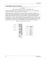
Incremental quadrature encoder feedback input
Servo
6-Pin Screw Terminal
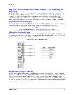
Amplifier command output (DAC
)
), amp enable output, and amp fault input
Flags
5-Pin Screw Terminal
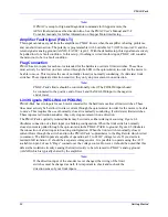
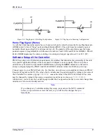
Axis overtravel limits & home flag input
JOPT Output
11-Pin Screw Terminal
Eight general purpose outputs
JOPT Input
11-Pin Screw Terminal
Eight General purpose inputs
FLT
RELAY
3-Pin Screw Terminal
PMAC Fault (Watchdog) Output (Normally closed
and
Normally open
Outputs)
JDISP
15-Pin D-Sub Connector PMAC Display Output (For use with any of the family of ACC12 Displays)
JPAN
25-Pin D-Sub Connector PMAC Panel interface connector. (Inputs such as: Axis Select, Jog, Home,
Run, Abort, Reset. Outputs such as: Following error, In position, buffer full.)
JTHW
25Pin D-Sub Connector
PMAC Multiplexer port connector. Used for interconnection of additional I/O
(PMAC ACC27, ACC34), Thumb wheel inputs (PMAC ACC 18), and power
on position information.
JRS232 DB9
Connector
Standard RS232 Interface for communication to PMAC. (Non-functional
when optional RRS422 interface ordered, OPT-9LPP) . This serial
interface does not support multi-drop tri-state communication to
multiple PMAC-Packs.
JRS422 25-Pin
D-Sub
Connector
Optional RS422 Interface for communication to PMAC. Supports multi-drop
tri-state communication to multiple PMAC-packs on single serial cable.
(Requires PMACPACK OPT-9LPP. JRS232 port is rendered non-functional.)
JANA
15-Pin D-Sub Connector Analog input port connector, only active when PMAC-Pack is equipped with
ACC28PP. Provides interface for 4 analog inputs, isolated power.
JEXP
50-Pin Box Header
Expansion port for connection of ACC24EXP, PMAC ACC14, or other
PMAC accessories which connect directly to the microprocessor bus.
TBOUT
12-Pin Screw Terminal
Four Channels of DC Motor Outputs, 48 V Amplifier DC bus input, dynamic
braking resistor output
JHW
9-Pin D-Sub Connector
Inputs for one channel of incremental quadrature encoder feedback.
Switches and Indicators
PMAC-Pack is equipped with the following switches and indicators:
Communications
Switch Bank
This bank of 8 DIP-switches sets the serial communications baud rate. Additionally it controls the "card
address" for use in addressing multiple PMACPacks.
RE-INIT
Re-Initialization — This switch, if depressed on power up, reinitializes PMAC's software to the factory
default state. PMAC only concerns itself with the status of this switch upon power up. (The Switch is tied
to PMAC's "E51" Jumper).
PWR
The Green "Power" LED should illuminate when AC power is applied to PMAC-Pack.
WDT
The Red Watch Dog Timer LED will illuminate when there is a serious fault within PMAC. Consult
Chapter 4 of this manual for further detail on the conditions leading to this fault.
OPWR
The orange Opto Isolation Power LED embedded in the edge of the JOPT-OUTPUT connector will
illuminate when power (+12 to +24V) is applied to the O+V (pin 2 of the JOPT-OUTPUT port).
Summary of Contents for PMAC Pack
Page 10: ...PMAC Pack Table of Contents vii ...
Page 11: ......
Page 16: ...PMAC Pack Overview 5 Figure 1 1 PMAC Pack Dimension ...
Page 27: ...PMAC Pack 16 Overview ...
Page 47: ...PMAC Pack 36 Getting Started ...
Page 51: ...PMAC Pack 40 Complying with European Community EMC Requirements ...
Page 53: ...PMAC Pack 42 PMACPack Custom Configuration Figure 4 1 PMAC Pack Disassembly ...
Page 70: ...PMAC Pack PMACPack Custom Configuration 59 Figure 4 4 PMAC Pack Assembly ...
Page 91: ...PMAC Pack 80 Circuit Diagrams Figure 7 2 Basic PMAC Pack Wiring Diagram ...
Page 92: ...PMAC Pack Circuit Diagrams Figure 7 3 PMAC Pack with Accessory 8D Option 2 Wiring Diagram ...
Page 93: ...PMAC Pack 82 Circuit Diagrams Figure 7 4 PMAC Pack with Accessory 8D Option 4A Wiring Diagram ...
Page 94: ...PMAC Pack Circuit Diagrams Figure 7 5 PMAC Pack with Option 9L Wiring Diagram ...
Page 95: ...PMAC Pack 84 Circuit Diagrams Figure 7 6 PMAC Pack with Accessory 28A Wiring Diagram ...
Page 96: ...PMAC Pack Circuit Diagrams Figure 7 7 PMAC Pack with Accessory 39 Wiring Diagram ...
Page 97: ...PMAC Pack 86 Circuit Diagrams ...
Page 98: ...PMAC Pack Circuit Diagrams 87 ...
Page 99: ...PMAC Pack 88 Circuit Diagrams ...
Page 100: ...PMAC Pack Circuit Diagrams 89 ...
Page 101: ...PMAC Pack 90 Circuit Diagrams ...
Page 103: ...92 Acc 24E Acc 24EXP Expansion XP Pack Figure 8 1 Expansion Pack Installation ...
Page 106: ...PMAC Pack Acc 24E Acc 24EXP Expansion XP Pack 95 Figure 8 3 PMAC Pack Assembly ...
Page 109: ...98 Acc 24E Acc 24EXP Expansion XP Pack ...


