PRODUCT REFERENCE GUIDE
203
Device Settings | Camera #n | Serial Port
Use the Serial Port menu tree selections to set up communications through the serial
Port. If necessary, you can later make modifications to the device settings using the
same menu selections, including:
Focus | Host Port Settings
Use the
Focus Port
window to configure communication between the camera and the
focusing device. The focus port is only used to match the focus device’s communication
configuration (light curtain, DM3610).
To edit the Focus Port settings:
1. In the menu tree under
Modify Settings,
navigate to
Modify Settings | Device
Settings | Camera N | Focus | Host Port Settings
. The
Focus | Host Port Settings
window opens.
2. Enter the appropriate information in the form as described below:
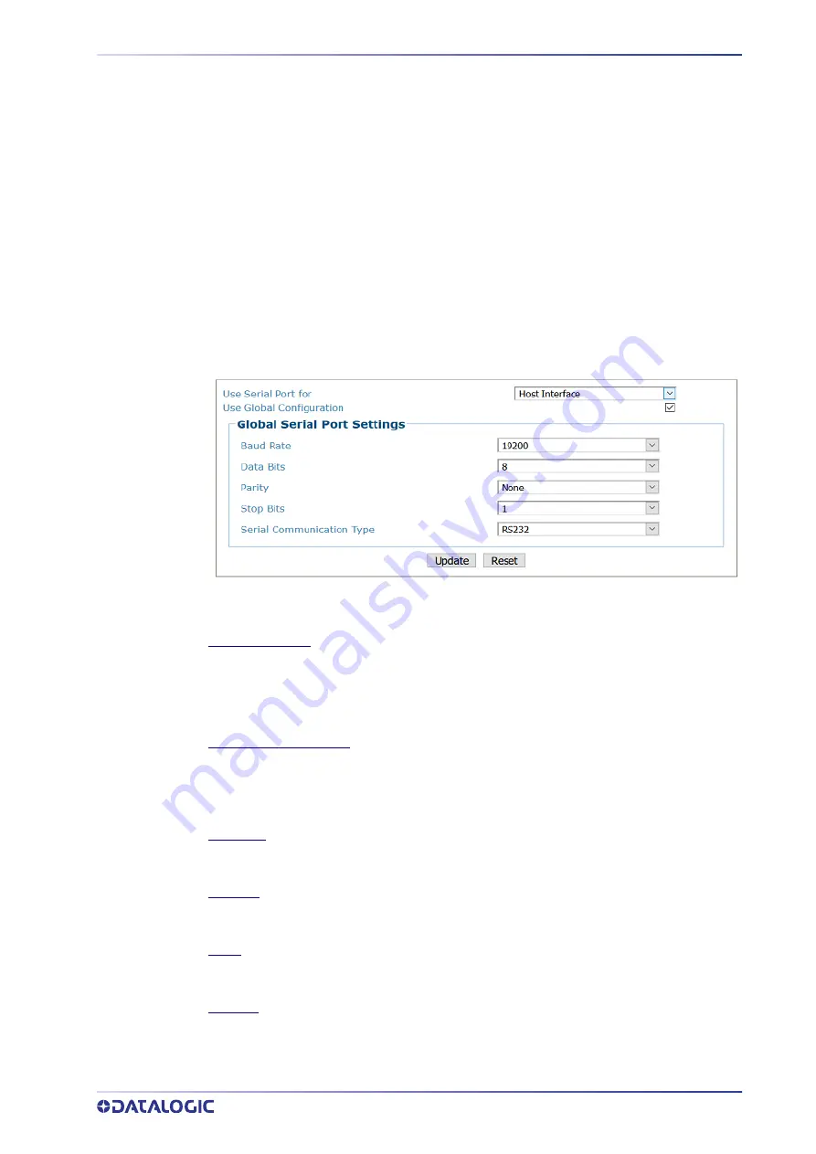
Use Serial Port for
Select one of the following from the drop
‐
down:
Host Interface:
The Host Interface is used to communicate with the customers serial
interface. The AV500 can either communicate RS232 or RS422.
Focus Input:
The Focus Input is used to communicate with the focus device.
Use Global Configuration
Select the check box when using a serial focus device for one or more cameras. When the Use
Global Configuration is selected all AV500's in the array can identify the Serial message from
the Host/Focus input.
When it is not selected the menu will give the option of selecting a single AV500 in the array.
Baud Rate
Select a value from 1200 to 115200 from the drop
‐
down list. Baud Rate is the transmission
speed in a communication line.
Data Bits
Select 7 or 8 from the drop
‐
down list. Data Bits is a parameter indicating the number of bits
composing the data packet of the communication protocol frame.
Parity
Select None, Odd, or Even from the drop
‐
down list. Parity is a parameter indicating the
presence of a control bit in the communication protocol frame.
Stop Bits
Select 1 or 2 from the drop
‐
down list. Stop Bits is a parameter indicating the number of stop
bits in the data packet of the communication protocol frame.
Summary of Contents for AV500
Page 1: ...AV500 PRODUCT REFERENCE GUIDE 2D CAMERA...
Page 53: ...MOUNTING PRODUCT REFERENCE GUIDE 33...
Page 73: ...CBX510 CONNECTION BOX PRODUCT REFERENCE GUIDE 53 Photoelectric Sensor to CBX510 NPN...
Page 74: ...ELECTRICAL INSTALLATION 54 AV500 2D CAMERA Photoelectric Sensor to CBX510 PNP...
Page 84: ...ELECTRICAL INSTALLATION 64 AV500 2D CAMERA Photoelectric Sensor to CBX100 and CBX800 NPN...
Page 86: ...ELECTRICAL INSTALLATION 66 AV500 2D CAMERA...
Page 91: ...FOCUSING DEVICE WIRING PRODUCT REFERENCE GUIDE 71 Unpowered Outputs...
Page 113: ...OPERATING MODE PRODUCT REFERENCE GUIDE 93...
Page 203: ...PRODUCT REFERENCE GUIDE 183 12 Click Next Step and the following screen appears...
Page 205: ...PRODUCT REFERENCE GUIDE 185...
Page 218: ...E GENIUS 198 AV500 2D CAMERA...
Page 230: ...E GENIUS 210 AV500 2D CAMERA...
Page 231: ...PRODUCT REFERENCE GUIDE 211...
Page 234: ...E GENIUS 214 AV500 2D CAMERA...
Page 249: ...PRODUCT REFERENCE GUIDE 229...
Page 253: ...PRODUCT REFERENCE GUIDE 233...
Page 260: ...E GENIUS 240 AV500 2D CAMERA...
Page 266: ...E GENIUS 246 AV500 2D CAMERA...
Page 299: ...AV500 CALIBRATION PRODUCT REFERENCE GUIDE 279...
Page 321: ...NOTES...
Page 322: ...NOTES...
Page 323: ...NOTES...