Installation and operation manual
94
EKEQMCBV3
Option kit for combination of Daikin condensing units
with field supplied air handling units
4PW52447-1
I
NSTALLATION OF THERMISTORS
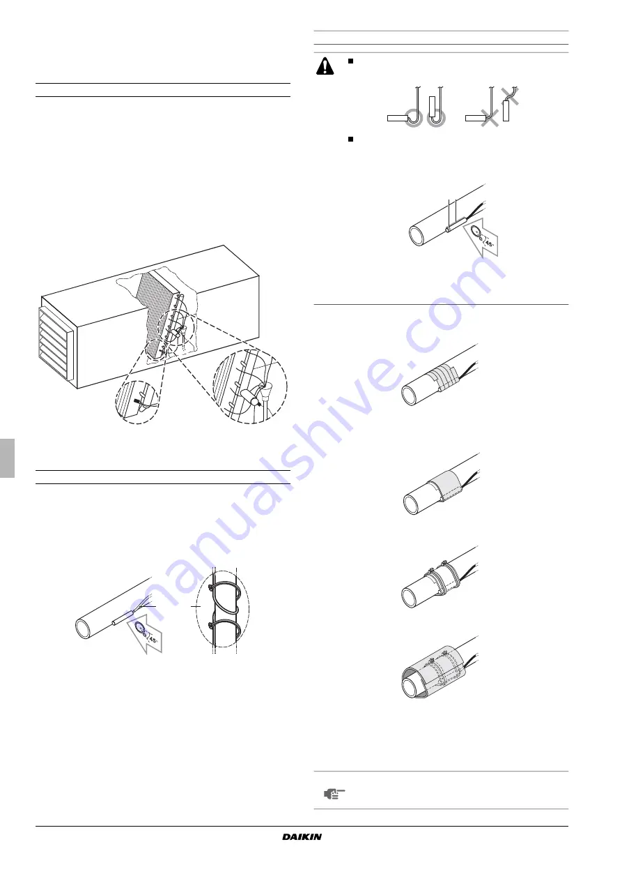
Refrigerant thermistors
Location of the thermistor
A correct installation of the thermistors is required to ensure a good
operation:
1.
Liquid (R2T)
Install the thermistor behind the distributor on the coldest pass
of the heat exchanger (contact your heat exchanger dealer).
2.
Gas (R3T)
Install the thermistor at the outlet of the heat exchanger as close
as possible to the heat exchanger.
Evaluation must be done to check if the air handling unit is protected
against freeze-up.
Execute test operation and check for freeze-up.
Installation of the thermistor cable
1
Put the thermistor cable in a separate protective tube.
2
Always add a pull-relief to the thermistor cable to avoid strain on
the thermistor cable and loosening of the thermistor. Strain on
the thermistor cable or loosening of the thermistor may result in
bad contact and incorrect temperature measurement.
Fixation of the thermistor
1
Fix the thermistor with insulating aluminum tape (field supply) in
order to ensure a good heat transference.
2
Put the supplied piece of rubber around the thermistor
(R2T/R3T) in order to avoid loosening of the thermistor after
some years.
3
Fasten the thermistor with 2 tie wraps.
4
Insulate the thermistor with the supplied insulation sheet.
Air thermistor
The air thermistor (R1T) can be installed either in the room that
needs temperature control or in the suction area of the air handling
unit.
1
Liquid R2T
2
Gas R3T
1
2
Put the thermistor wire slightly down to avoid water
accumulation on top of the thermistor.
Make good contact between thermistor and air
handling unit. Put the top of the thermistors on the air
handling unit, this is the most sensitive point of the
thermistor.
NOTE
For room temperature control the delivered thermistor
(R1T) can be replaced by an optional remote sensor kit
KRCS01-1(A) (to be ordered separately).
2
1
1
Most sensitive point of the thermistor
2
Maximize the contact
Summary of Contents for ERQ Series
Page 2: ......
Page 16: ...Combination Table ESiEN09 06 A 6 General Information...
Page 17: ...ESiEN09 06 A Specifications 7 1 Specifications 8 1 1 Outdoor Units 8...
Page 33: ...ESiEN09 06 A Function general Function 23 1 2 Operation Mode...
Page 58: ...Outline of Control ESiEN09 06 A 48 Function...
Page 71: ...ESiEN09 06 A Wiring Diagram of Control Box Control Box EKEQ CBV3 61 3 2 F box...
Page 109: ...Test Operation ESiEN09 06 A 100 Test Operation 1 2 2 Turn power on...


