background image

 
Page 48 

CET-16 Service Manual 

WEEKLY MAINTENANCE


WARNING


The steamer is equipped with a drain screen i

n

 the back 

of the cooking compartment. The steamer should never 
be operated without the screen in place. This screen 
prevents large food particles from entering and possibly 
blocking the drain fine. Any blockage of the drain fine 
may cause a slight buildup of back pressure in the 
compartment resulting in steam leaks around the door 
gasket. It also may adversely affect the convection 
action of the steam in the compartment, which is neces-
sary for optimum performance. 

1

.

 Make sure the drain screen and drain line are not blocked. Pour USDA 

approved drain cleaner through drain once a week. 

2

.

 Inspect for steam generator scale weekly. The frequency of steam 

generator descaling depends upon water quality and daily steam 
generator drain and washout. If steam generator scale buildup is a 
frequent problem, install a water treatment system for the steamer. See 
Water Quality Requirements on page 6. 

3. Regardless of use, steam generator should be descaled at least once a 

month.  See Steam Generator Descaling Procedure below. 


YEARLY MAINTENANCE


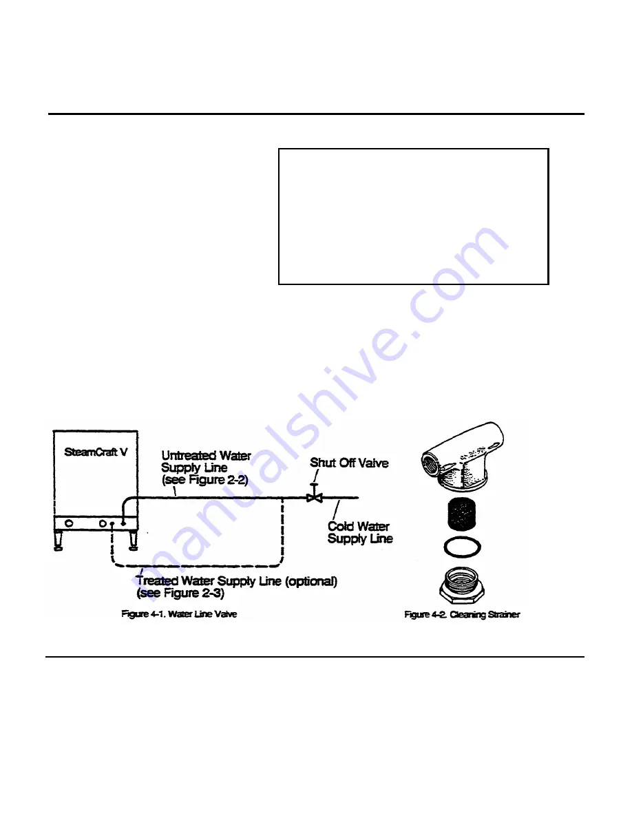
Clean the water line filter at least once a year as follows: 

1. Close the valve in the steamer water line

.

 Refer to figure 4-1. 

2.

 Unscrew the filter from the bottom of the strainer which is located in 

back of the steamer. Refer to figure 4-2. 


Printed 4/90


Summary of Contents for SteamCraft V

Page 1: ...990 Cleveland Range UNITED STATES CANADA 1333 East 179th St Cleveland Ohio 44110 8251 Kelle St Concord Ontario Canada L4K 1Z1 Phone 216 481 4900 Telex 98 0546 Phone 416 660 4747 Fax 416 660 4492 Fax 2...

Page 2: ...g Damage Instructions 14 Assembly 14 Install The Steam Generator Cover 14 Install The Fan Guard 14 Install The Slide Racks 15 Install The Water Strainer 15 Position and Level SteamCraft V 16 Connect E...

Page 3: ...IMED Cooking 43 MANUAL Cooking 43 SHUT DOWN At end of day or shift 43 CHAPTER 4 PREVENTATIVE MAINTENANCE AND TROUBLSHOOTING 47 INTRODUCTION 47 MAINTENANCE RECORDS 47 DAILY MAINTENANCE 47 WEEKLY MAINTE...

Page 4: ...Troubleshooting 64 WATER LEVEL PROBES 64 Set Point 64 Water Level Control Testing 65 Flood Probe Control Circuit 65 Water Level Probe Control Circuit 65 Low Water Level Control Circuit 66 TEMPERATURE...

Page 5: ...Page 0 CET 16 Service Manual Figure 1 1 SteamCraft V Counter Type Convection Steamer Printed 4 90...

Page 6: ...sign information The right half of the number contains the manufacturing date and the unit of the manufacturing lot The date of our sample number is July 1989 89 1989 G July 02 the second unit of the...

Page 7: ...iew and Preparation For Installation Responsibility for feed water quality and its testing as described in Preparation for Installation Water Quality WARNING DEATH INJURY AND EQUIPMENT DAMAGE could re...

Page 8: ...comply with these codes In no event shall the manufacturer assume any liability for damage or injury resulting from installations which are not in strict compliance with the Installation Instructions...

Page 9: ...The steamer MUST be electrically grounded by the Installer 4 Untreated cold water connection 1 4 NPT Steam Generator and Condenser supply for units without water treatment system Condenser supply for...

Page 10: ...bes and solenoid valves Of equal importance is the toss of energy efficiency due to line or scale buildup In these areas either a Steamer Gard water treatment system must be installed or time frequenc...

Page 11: ...When selecting an operating location for the SteamCraftV observe the following criteria The SteamCraft V takes up a minimum of counter space Figure 2 4 illustrates the dimensions and clearances requi...

Page 12: ...of approximately 150 pounds to include the weight of water and food The SteamCraft V has capacity for five 12 x 20 x 2 5 Cafeteria Pans model SP 25 or PP 25 Convenient storage for these pans and thei...

Page 13: ...ith local codes and or the National Electric Code ANSI NFPA No 70 1990 USA 2 In Canada install the electrical power lines in accordance with local codes and or the Canadian Electrical Code CSA Standar...

Page 14: ...ly fines observe the following instructions 1 Always connect a COLD water supply to the condenser steam gener ator connection item 4 figure 2 1 If hot or warm water is supplied to this connection the...

Page 15: ...a back pressure or a vacuum within the SteamCraft V Backpressure will cause steam and hot water leakage around the door A vacuum will implode the steamer Furnishing and plumbing the drain lines is th...

Page 16: ...umulative length of pipe and or number of elbow fittings required to reach the open drain If the drain outlet extension requires six feet or less of pipe and no more than two elbows are required use 1...

Page 17: ...carton sides away from the SteamCraft V 3 Open the door of the SteamCraft V and remove the package of unassembled parts This package contains the four parts illustrated in figure 2 8 Check that all f...

Page 18: ...g to the following instructions Install The Steam Generator Cover 1 Refer to figure 2 10 and hold the steam generator cover with the short handle to the left and the long handle to the right The print...

Page 19: ...top pins then hook the bottom loops over the two bottom pins 4 Repeat steps 1 through 3 for the other rack Install The Water Strainer As illustrated in figure 2 l3 the water strainer is supplied with...

Page 20: ...ll Preparation Tasks are complete Check that all Unpacking and Assembly tasks are complete 2 Looking at the counter where the SteamCraft V will be placed estimate the location of the four corners that...

Page 21: ...to the electrical conduit access note figure 2 15 See Canadian Wiring Considerations below 4 The terminal block and ground connection are near the left side of the rear opening The unit has either a...

Page 22: ...ing to Water Supply Lines page 10 and figure 2 2 verify that the water supply line has been extended to the SteamCraft V properly Connect the supply line to the SteamCraft V as described below 1 If th...

Page 23: ...tached to the tee and bulkhead coupling inside the steamer Verify that the steam generator supply outlet of the tee has been securely capped 5 Flush the water supply line before connecting it to the s...

Page 24: ...ing 6 Apply pipe dope or teflon tape to the threads of the treated water supply fine and securely connect the supply fine to the steam gener ator intake bulkhead coupling 7 Turn on the treated water s...

Page 25: ...raft V The test also verifies basic operation of the steamer For a more complete test of the SteamCraft V functions perform the Function Test on page 23 Setup 1 Refer to Assembly page 14 and verify th...

Page 26: ...pad The red light above POWER and the WATER alarm light turn on Water begins to fill the steam generator The low water indicator WATER remains on until the steam generator is filled with enough water...

Page 27: ...r win turn on and start generating steam 5 Open the steamer door The compartment should again be filled with steam 6 It necessary repeat this test to be sure the steam shuts off when the door opens an...

Page 28: ...nd Check Out procedures If the checkout has been unsatisfactory or a more thorough inspection is required perform the following Function Test procedures Flow Leak and Flood Test 1 Do not remove the co...

Page 29: ...d drain Check for water leakage at pipe joints and tube connections or unions Wait for a few minutes then look for water leaking from the steam generator Repair any leaks before continuing 5 As illust...

Page 30: ...rs and fan motor turn on 3 Check for condenser water flow from the drain 4 Open the steamer door The condenser valve three heaters one contactor and fan motor turn off 5 Set a magnet over the door swi...

Page 31: ...8 8 The TIME DISPLAY counts down to 00 an alarm beeps four times and the TIME DISPLAY flashes 00 9 The heaters fan and condenser valve turn off 10 Press the TIMED touch pad 6 to stop displays 11 Set...

Page 32: ...he checkout has been unsatisfac tory or a more thorough inspection is required perform the following Function Test procedures Flow Leak and Flood Test 1 Do not remove the control panel unless it is ne...

Page 33: ...er and drain Check for water leakage at pipe joints and tube connections or unions Wait for a few minutes then look for water leaking from the steam generator Repair any leaks before continuing 5 As i...

Page 34: ...he control panel Differences in heater outputs are observed daring this procedure To emphasize these differences start this procedure with cold water in the steam generator it may be necessary to drai...

Page 35: ...pad 2 The heaters fan and condenser valve turn on 15 Pressing MANUAL overrides the timer Unit will remain unopened until the MANUAL touch pad is pressed again Automatic timer can be used during MANUAL...

Page 36: ...SteamCraft V will require minimum servicing if it is properly operated and maintained by trained personnel The following steps will help keep the steamer in good condition 1 Conduct regular steamer in...

Page 37: ...IMESET The left and right TIME SET touch pads set the DIGITAL TIME DISPLAY A maximum of 99 minutes can be programmed using the left and right TIME SET touch pads 4 TIME SET 10 Minute Left The left TIM...

Page 38: ...tor fills to the proper level 9 DIGITAL TIME DISPLAY The DIGITAL TIME DISPLAY shows cooking time When MANUAL cooking is selected the TIME DISPLAY counts up from 00 so the operator can watch elapsed ti...

Page 39: ...TIME DISPLAY A maximum of 99 minutes can be programmed using the left and right TIME SET touch pads 4 TIME SET 10 Minute Left The left TIME SET touch pad sets the DIGITAL TIME DISPLAY in 10 minute seg...

Page 40: ...tor fills to the proper level 9 DIGITAL TIME DISPLAY The DIGITAL TIME DISPLAY shows cooking time When TIMED cooking is selected the TIME DIS PLAY counts down from the time set using the left and right...

Page 41: ...rneath the steamer near the leftft rear comer see figure 3 3 Push the handle to the right to dose the dram valve Pull the handle toward the front of the steamer to open the drain valve The drain valve...

Page 42: ...DIGITAL TIME DISPLAY flashes 00 and a signal beeps four times TIMED MODE After S N WC 9018 90A 05 TIMED mode is used when the operator wishes to set the timer for a specific length of cooking time fo...

Page 43: ...is done 1 Pressing the MANUAL touch pad starts steamer manual cooking The green light above the touch pad tuns on 2 When correct cooking time has elapsed pressing the MANUAL touch pad a second time st...

Page 44: ...roper level If the FLOOD or WATER alarm does not turn off when the water level is corrected 1 Open the drain valve 2 Wash out the steamer compartment and steam generator 3 Descale the steam generator...

Page 45: ...er PP 2 5 This gives the best heat transfer and shortest cooking time for the food 5 Select either TIMED or MANUAL cooking Refer to TIMED and MANUAL cooking instructions that follow WARNING SEVERE BUR...

Page 46: ...touch pad turns on 3 Food starts cooking 4 At end of cooking time press the MANUAL touch pad again The green light above the touch pad turns off 5 Carefully open steamer door and remove food This proc...

Page 47: ...dishwasher according to health requirements 5 Before draining while water is still warm use a very soft brush to brush down the probes generator walls and elements to remove accumulated scale before i...

Page 48: ...gain Clogged or slow drains are dangerous because hot water may spill out when compartment doors are opened during or after a cooking cycle 9 Wipe the exterior a damp cloth only Do not hose down equip...

Page 49: ...warm brush the generator out with a very soft brush going over the probes elements and sides This removes scale before it hardens and prevents scale buildup Drain the steam generator at least twice a...

Page 50: ...creen and drain line are not blocked Pour USDA approved drain cleaner through drain once a week 2 Inspect for steam generator scale weekly The frequency of steam generator descaling depends upon water...

Page 51: ...properly Follow these basic safety rules for handling and using acid Wear protective clothing when mixing or apply ing chemical cleaners Wear rubber gloves mask and approved cup type goggles Avoid br...

Page 52: ...rator so cover will also be descaled 10 Leave acid in the steam generator for at least 1 1 2 hours Full descaling may take several hours depending upon the amount of scale buildup If add is consumed b...

Page 53: ...te 3 Unit may need new flood probe retrofit kit Contact service representative Water solenoid or controls inoperative Turn electricity and water off and refer to note 1 Steam coming from drain hub Wat...

Page 54: ...level cooking Extend cooking times for altitudes above 2500 feet Cabinet bottom dirty with food drippings Juices and or food leaking from perforated trays Put a solid tray under perforated trays to ca...

Page 55: ...tructions in Chapter 3 Operation 4 Repairs to external wiring should be done by a Licensed Electrician 5 Repairs to external plumbing should he done by a Licensed Plumber 8 Proper installation of the...

Page 56: ...Page 54 CET 16 Service Manual Figure 5 1 Block Diagram Printed 4 90...

Page 57: ...r element The 120 VAC circuit draws its power from the 120 VAC secondary windings of the transformer This circuit supplies power to contactors and solenoids which control high voltage and water flow T...

Page 58: ...own transformer most be wired in paraIlel 2 For operation at 440 480 VAC the primary windings of the stepdown transformer must be wired in series 3 Steam generator and fan heater elements are availabl...

Page 59: ...CET 16 Service Manual Page 57 Figure 5 2 Control Board Printed Circuit Board Printed 4 90...

Page 60: ...the resistance of the beater element and compare the results to the values in Tables 5 1 and 5 2 for the particular part number being tested 5 When testing an element known to be good it is possible...

Page 61: ...k power from the control board to the front or rear contactors energized measure the voltage 120 VAC nominal across the ter minals at the contactor The exposed contactor terminalsor the capacitor lead...

Page 62: ...energizes during standby steaming cycles The SteamCraft V operates in standby anytime the steamer has been ener gized by pressing the POWER switch on the front panel the door is closed and the water...

Page 63: ...s connection to protect it from moisture and to maintain its secure contact with the control board If CON 1 must be disconnected to test the switch panel take care when reinserting the connector so th...

Page 64: ...mity switch activated by a magnet mounted inside the compartment door The control circuitry prevents operation of heater elements and the condenser solenoid valve while this snitch is open door open T...

Page 65: ...temperature to drop below the switch set point the switch prevents the timer from starting its countdown until the compartment temperature rises and the switch closes Also if the door opens during a...

Page 66: ...the rear contactor starts to cycle OFF and ON After the compartment heats up and the switch closes turn the steamer OFF and open the steamer door The switch should open within 2 minutes If the switch...

Page 67: ...l Testing To test the operation of water level sensing functions use a multimeter or ohmmeter and a 100 000 ohm potentiometer to check resistance Refer to test procedures below for function to be test...

Page 68: ...2 Refer to me wiring diagram see Table 6 1 Disconnect the black wire from the low water level probe probe nearest rear 3 Using a meter set the resistance of the potentiometer to 20 000 Ohms 4 With pr...

Page 69: ...er for set point adjustment Replacement of either thermoistor the control board requires calibration of BOTH temperature control circuits The operation of both the generator temperature adjustment cir...

Page 70: ...se temperature Set the control so the water temperature remains approximately l90 F Being careful not to contact the heater elements measure the water temperature with a thermometer Drain Temperature...

Page 71: ...gative temperature coefficient thermistor decreases as temperature increases To test a thermistor connect an ohmmeter to the thermistor leads and observe the changes in resistance as the thermistor is...

Page 72: ...This assembly contains the latest version of toe control panel Once this is installed the unit will operate in the same manner as all units after serial number WC 9018 90A 05 Figure 6 1 identifies the...

Page 73: ...Page 72 CET 16 Service Manual Figure 6 1 MAJOR COMPONENT GROUPS...

Page 74: ...ess Panel 1 2 19148 Screw Panel Mounting 6 3 101622 Decal Drain Specification 1 4 101795 Decal Electrical Schematic Standard US Units 1 101966 Decal Electrical Schematic 4 Wire Connection 1 101966 Dec...

Page 75: ...nual Figure 6 3 STEAMER COMPARTMENT GROUP Item Part No Description Quantity 1 Circular Oven Element Assembly See Figure 6 7 For Parts 1 2 101436 Cover Fan 1 3 414232 Rack Slide 2 4 1012881 Cover Steam...

Page 76: ...5 18357 Pop Rivet Mounting Internal Door Plate 12 COMPARTMENT DOOR HINGE ASSEMBLY 6 101357 Bracket Compartment Door Hinge 1 7 101334 Screw 10x32 Pan Head 2 8 101355 Rod Compartment Door Hinge 1 9 101...

Page 77: ...1 3 102411 Door Inner 1 4 101401 Gasket Inner Door 1 5 102513 Washer Rat 2 6 19923 Pin Mounting Inner Door 2 7 102000 Hinge Door Top 1 8 102001 Hinge Door Bottom 1 9 101334 Screw 10 x 32 Pan Head 2 DO...

Page 78: ...Switch and Control Board 1 4 Membrane Switch 1019301 1 5 Printed Circuit Board Control Panel PCB 101606 1 6 Magnet Compartment Door Sensor 101684 1 7 Bracket Magnet Mounting 101710 1 8 Nut 8 x 32 Hex...

Page 79: ...ing 1 THERMOSWITCH ASSEMBLY 13 101543 Thermoswitch Snap Disc 1 14 101643 Nut Mounting Thermoswitch 2 15 23111 Washer Star 2 THERMAL SENSOR ASSEMBLY 16 101508 Sensor Thermal 1 17 102348 Bracket Mountin...

Page 80: ...CET 16 Service Manual Page 79 Figure 6 6 ELECTRICAL COMPONENTS ASSEMBLY Printed 4 90...

Page 81: ...01235 208 240V Single Phase 1012351 440 480V Single Phase 9 102264 Seal Motor Shaft 1 10 19288 Bolt Motor Mounting 4 11 23105 Lockwasher 4 12 101676 Bolt Fan to Motor Mounting 1 13 23106 Lockwasher 1...

Page 82: ...CET 16 Service Manual Page 81 Figure 6 7 FAN ASSEMBLY Printed 4 90...

Page 83: ...1320 Stud Threaded Mounting 10 32 1 10 102424 Duckbill 1 11 14497 Nozzle Condenser Brass 1 12 06231 Fitting 1 4 tube x 1 8 FPT 90 Brass 1 13 14401 Nipple Pipe Drain Extension 1 1 4 LP S x 9 5 1 14 202...

Page 84: ...CET 16 Service Manual Page 83 Figure 6 8 CONDENSER AND DRAINAGE SYSTEMS Printed 4 90...

Page 85: ...er Heater 515 I D Zinc PL 8 9 101308 Nut Hex Brass 1 4 20 8 10 1013121 Spacer Heating Element 1 11 14677 Nut Acorn 1 4 20 S S 1 12 102519 LOW WATER PROBE ASSEMBLY 1 13 1022532 Probe Weldment Assembly...

Page 86: ...CET 16 Service Manual Page 85 Figure 6 9 STEAM GENERATOR ASSEMBLY Printed 4 90...

Page 87: ...ression rating 1 4 MPT 4 11 22218 Valve Condenser Solenoid 1 4 120V 1 12 1024862 Tubing Condenser 24 13 102431 Coupling Assembly Bulkhead 1 4 Female 1 14 Adapter Coupling 1 15 Nut Coupling Retainer 1...

Page 88: ...CET 16 Service Manual Page 87 Figure 6 10A DOUBLE WATER INLET ARRANGEMENT Printed 4 90...

Page 89: ...Insert 1 4 Tubing 8 10 1024862 Tubing Condenser 24 11 06214 1 4 Tube 90 Compression Fitting 1 4 MPT 4 12 22218 Valve Condenser Solenoid 1 4 120V 1 13 1024862 Tubing Condenser 24 14 1024862 Tubing 1 4...

Page 90: ...CET 16 Service Manual Page 89 Figure 6 10B SINGLE WATER INLET ARRANGEMENT Printed 4 90...

Page 91: ...ube 90 Compression Fitting 1 4 MPT 4 12 22218 Valve Condenser Solenoid 1 4 120V 1 13 1024862 Tubing Condenser 24 14 16619 Fitting 1 4 Plug 1 15 102431 Coupling Assembly Bulkhead 1 4 Female 1 16 Adapte...

Page 92: ...CET 16 Service Manual Page 91 Figure 6 10C DOUBLE WATER INLET ARRANGEMENT WITH STEAMERGARD Printed 4 90...

Page 93: ...Page 92 CET 16 Service Manual Figure 6 11 SteamCraft V Wiring Diagram 3 Wire DELTA Connection Printed 4 90...

Page 94: ...CET 16 Service Manual Page 93 Figure 6 12 SteamCraft V Schematic Diagram 3 Wire DELTA Connection Printed 4 90...

Page 95: ...Page 94 CET 16 Service Manual Figure 6 13 SteamCraft V Wiring Diagram 4 Wire WYE Connection Printed 4 90...

Page 96: ...CET 16 Service Manual Page 95 Figure 6 14 SteamCraft V Schematic Diagram 4 Wire WYE Connection Printed 4 90...

Reviews: