c) Remove the top cover from the server as described in
Removing the Server Top Cover, on page 37
.
Step 2
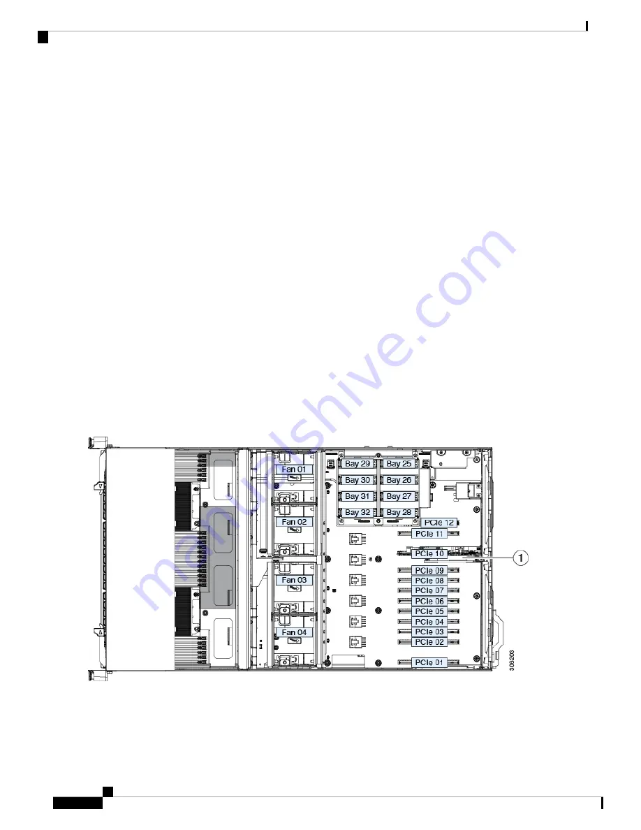
Remove any existing rear NVMe switch card from PCIe slot 10:
a) Disconnect the PCIe cable from the existing card.
b) Open the hinged retainer bar that covers the top of PCIe slot 10. See
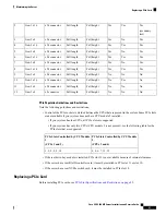
Replacing a PCIe Card, on page 91
.
Use your fingertips to pull back on the wire locking-latches at each end of the retainer bar, and then hinge the bar
open to expose the tops of the PCIe slots.
c) Open the card's blue ejector lever to unseat it from PCIe slot 10.
d) Pull both ends of the card vertically to disengage the card from the socket, and then set it aside.
Step 3
Install a new rear NVMe switch card:
a) Carefully align the card edge with the socket of PCIe slot 10.
b) Push on both corners of the card to seat its connector in the socket.
c) Fully close the blue ejector lever on the card to lock the card into the socket.
d) Connect the PCIe cable (CBL-AUX-NVME-M5) from the internal drive module backplane to the new switch card.
e) Close the hinged retainer bar over the top of the PCIe slots.
Use your fingertips to pull back on the wire locking-latches at each end of the retainer bar, and then hinge it closed
to lock in the tops of the PCIe slots. Push the wire locking-latching back to the forward, locked position.
Step 4
Replace the top cover to the server.
Step 5
Reconnect power cords to all power supplies and then allow the server to boot to standby power mode (indicated when
the front panel Power button LED lights amber).
Step 6
Fully power on the server by pressing the Power button.
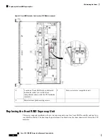
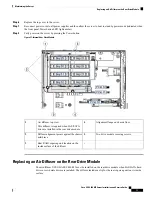
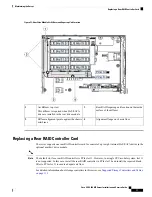
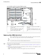
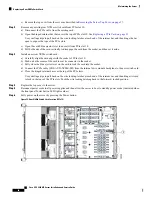
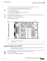
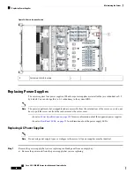
Figure 35: Rear NVMe Switch Card Location (PCIe 10)
Cisco UCS C480 M5 Server Installation and Service Guide
80
Maintaining the Server
Replacing a Rear NVMe Switch Card

