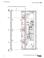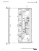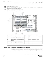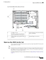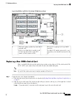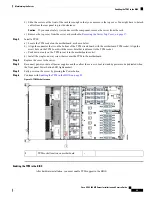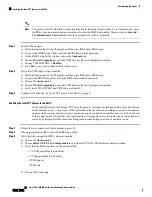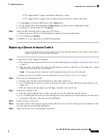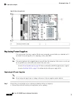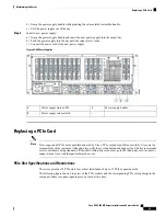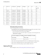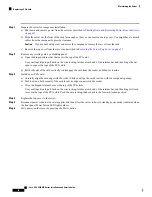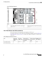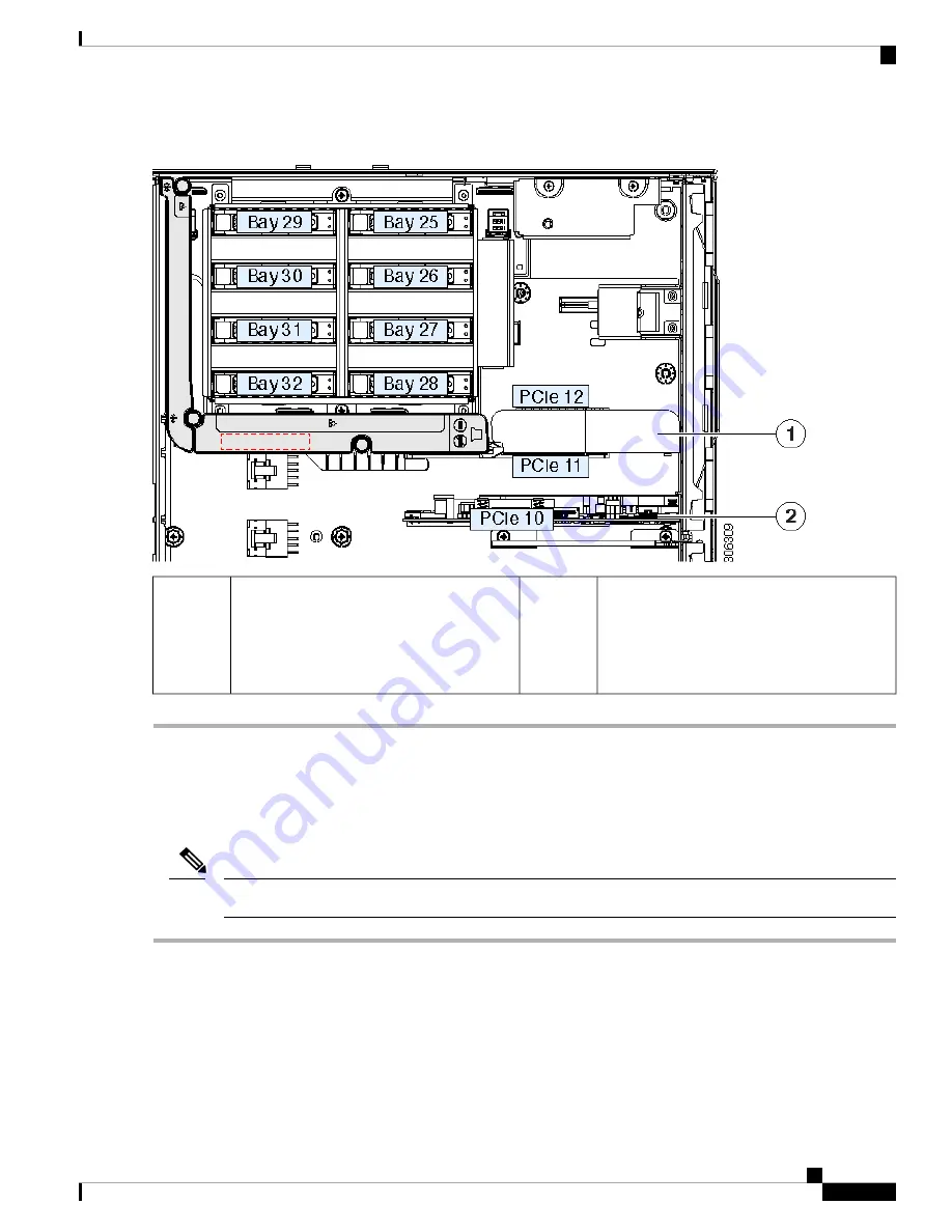
Figure 34: Rear RAID Card and PCIe Slot 11 Filler (Single CPU Module System Shown)
PCIe slot 10, secondary slot for rear RAID
controller
In a single CPU module system slot 11 is not
supported, so the controller must install to slot
10.
2
PCIe slot 11 (primary position for a rear RAID
controller card)
In this view, a blank filler is installed in slot
11. This is required only for single CPU
module systems to ensure air flow.
1
Replacing a Rear NVMe Switch Card
When you install NVMe drives in the rear drive-bay module, you must have an NVMe switch card in PCIe
slot 10. A PCIe cable connects the switch card to the drive-bay module backplane.
If a rear NVMe switch card is used, it must be installed in PCIe slot 10.
Note
Step 1
Prepare the server for component installation:
a) Shut down and remove power from the server as described in
Shutting Down and Removing Power From the Server,
on page 35
.
b) Slide the server out the front of the rack far enough so that you can remove the top cover. You might have to detach
cables from the rear panel to provide clearance.
If you cannot safely view and access the component, remove the server from the rack.
Caution
Cisco UCS C480 M5 Server Installation and Service Guide
79
Maintaining the Server
Replacing a Rear NVMe Switch Card

