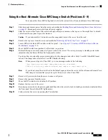
Step 3
Remove an existing Micro SD card:
a) Locate the Micro SD card.
b) Push horizontally on the Micro SD card and release it to make it spring out from the socket.
c) Grasp the Micro SD card and lift it from the socket.
Step 4
Install a new Micro SD card:
a) Align the new Micro SD card with the socket.
b) Gently push down on the card until it clicks and locks in place in the socket.
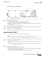
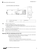
Figure 55: Micro SD Card Location Inside an I/O Module
-
Location of Micro SD card socket on the I/O
module board
1
Step 5
Return the I/O module to the chassis:
a) With the ejector-handle open, align the I/O module with the empty bay.
b) Push the module into the bay until it engages with the midplane connector.
c) Hinge the ejector-handle down until it sits flat and its locking clip clicks. The module face mst be flush with the rear
panel of the chassis.
d) Reconnect cables to the ports on the I/O module.
Step 6
Reconnect power cords to all power supplies and then allow the server to boot to standby power mode (indicated when
the front panel Power button LED lights amber).
Step 7
Fully power on the server by pressing the Power button.
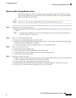
Replacing a Mini-Storage Module
The mini-storage module plugs into an I/O module board socket to provide additional internal storage. The
mini-storage module is available in two different versions:
• SD card carrier—provides two SD card sockets.
• M.2 SSD Carrier—provides two M.2 form-factor SSD sockets. These M.2 SSDs can be two SATA SSDs
(no mixing).
Cisco UCS C480 M5 Server Installation and Service Guide
114
Maintaining the Server
Replacing a Mini-Storage Module


