


88
ENG
pRack +0300025EN rel. 1.3 - 17.12.2015
A.2
Special confi gurations for subcritical CO
2
systems, cascade and pumped systems
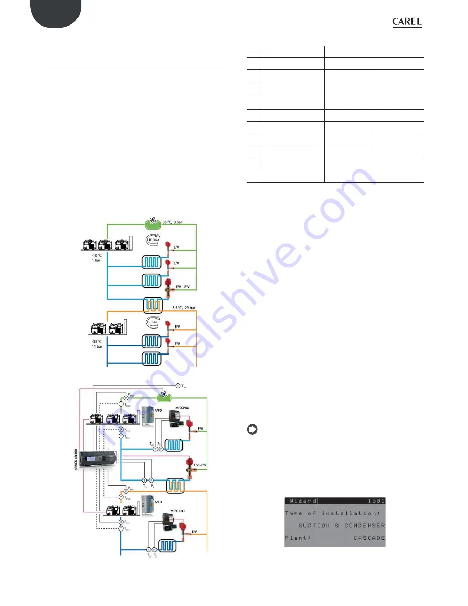
A.2.1 Cascade
The crucial aspect of this type of system is the cascade heat exchanger,
normally a plate heat exchanger, which controls the condensing stage of
the CO
2
system. At times there are two heat exchangers, so as to improve
control at low loads and increase safety, and these are normally controlled
by EXV electronic expansion valves with stepper motors. In these
applications, as well as traditional control based on suction superheat,
there is also integration with the low temperature rack, directly when
the rack controller has a built-in driver, or via serial communication for
external EVD EVO drivers. Given the nature of the refrigerant, condensed
liquid CO
2
needs to be monitored in order to ensure good performance
and protection. Up to 2 heat exchangers can be connected via Fieldbus
to the pRack controller, with a driver for each heat exchanger. The drivers
are connected to the board that manages the low temperature suction
line. Up to 6 control steps can be confi gured for connecting other drivers
controlled via digital input for superheat control. There can be maximum
two plate heat exchangers used to condense CO
2
, and the expansion valve
is managed using the built-in driver on pRack pR300 or external EVD EVO
driver suitably integrated into the system (Fieldbus communication over
RS485).
Fig. A.k
Fig. A.l
Legenda:
ac.
Description
Probe type
Notes
Text Outside temperature
NTC - HP
PD
L1
Discharge pressure line 1
(medium temperature)
4-20 mA 0-18.2 barg
TD
L1
Discharge temperature line 1
(medium temperature)
NTC - HF
To control discharge
temperature (opt.)
PS
L1
Suction pressure line 1
(medium temperature)
4-20 mA 0-7 barg
Can be used as backup
for PE
TSL1 Suction temperature line 1
(medium temperature)
NTC - HF
To control suction
superheat (opt.)
P
E
Heat exchanger evaporation
pressure
Ratiometric -1-9.3
barg
T
GS
Heat exchanger superheated
gas temperature
NTC – HF
PD
L2
Discharge pressure line 2
(low temperature)
4-20 mA 0-44.8 barg
TD
L2
Discharge temperature line 2
(low temperature)
NTC – HF
To control discharge
temperature (opt.)
PS
L2
Suction pressure line 2 (low
temperature)
4-20 mA 0-44.8 barg
TS
L2
Suction temperature line 2
(low temperature)
NTC - HF
To control suction
superheat (opt.)
Tab. 11.b
The exchange of information between compressor rack and heat
exchanger allows traditional superheat control to be augmented by
factors that are vital for this type of system, such as variation in low
temperature compressor rack cooling capacity and the trend in CO
2
condensing pressure. (pRack only sends the control parameters and the
cooling capacity to vary). The drivers connected via serial have advantages
over external confi gurations (via digital inputs) as the parameters are
easier to set (the driver screens can be accessed directly from the pRack
controller) and are more responsive when unit cooling capacity changes
considerably due to due peaks in demand. The drivers connected via
serial can use an estimated percentage of cooling capacity delivered by
the circuit to infl uence normal superheat control.
When the variation in capacity exceeds 10% or when control commences,
the driver pre-positions the valve to get closer to the optimum opening.
This operation ensures good control of condensing pressure on the low
temperature rack (S3 or A, confi gurable) when compressor on line 2
start. If the compressors on the low temperature rack are controlled by
inverter, capacity modulation will be much more linear and anticipation
of valve movements will have less infl uence (in terms of pre-positioning).
If using one or more single drivers, the condensing pressure probe can be
connected directly to the EVD EVO driver (S3), allowing just one pressure
probe to be used for condenser control and for the EVD EVO driver safety
procedure, which tends to open the valve when the CO
2
condensing
temperature is too high. In this case, the CO
2
condensing pressure probe
connected to pRack is optional.
This function can be used with the following confi gurations:
•
pRack pR300 with built-in driver and just one heat exchanger
•
pRack pR300 with single external EVD EVO driver
•
pRack pR300 with 2 single external EVD EVO drivers
•
pRack pR300 with 2 EVD EVO drivers, one of which built-in (only 1
exchanger) and 1 single external.
Note:
if serial communication between driver and pRack is interrupted,
the condensing pressure probe on the pRack, connected to the driver, will be
disconnected and the safety procedures featured on pRack will be activated
(alarm signal, use of the backup probe if confi gured, fan operation overridden
to a preset value). One DRIVER is needed for each valve; if a Twin Driver is used,
this will be managed as a single driver. The connection should be done on the
fi rst valve too (EXV1- J27 if a built-in driver is used).
Details of the pRack confi guration Wizard
After having selected this type of confi guration, the software takes a few
seconds to pre-confi gure some settings relating to a typical cascade
system, i.e. the second condenser line; the Wizard will prompt whether to
Summary of Contents for PRK300D0E0
Page 2: ......
Page 4: ......
Page 6: ...6 ENG pRack 0300025EN rel 1 3 17 12 2015...