


2. Installation
91
(16) Tool Modes (/np mode)
1) Purpose
The tool modes (startup options) are intended in order to check operation, and are used
to launch the CXDI software on the control computer by itself, and to display items that
are not normally displayed.
2) Notes
The following operation must be performed before using the “/np” mode. Especially, be
sure to back up the exposure mode names and the customized settings before the
operation.
2-1) When using “/np” with the same settings as that of the connected imaging unit
“BodyPart**.ini” file can be used as it is.
Example:
Connection
/np
setting
Sensor1 Table
Table
Sensor2 Stand
Stand
2-2) In case of using “/np” with different settings from that of the connected imaging unit
Move the “BodyPart**.ini” file in the “BodyParts” folder to the desktop, etc.
However, do not move the Reference folder. If the “BodyPart**.ini” file is left in the
“BodyParts” folder, system will not be able to be started, as the sensor type of the
“BodyPart” and the settings do not match.
Example:
Connection
/np
setting
Sensor1 Table
Table
Sensor2 Stand
Stand
3) Preparation
3-1) Connect the keyboard and the mouse to the control computer.
3-2) Delete the “ccrstart.bat” file from startup.
3-3) Disconnect the imaging unit from the control computer.
4) Startup
Method
4-1) Start up Windows XP.
4-2) Start the Command Prompt screen.
Start
⇒
Program
⇒
Accessories
⇒
Command Prompt
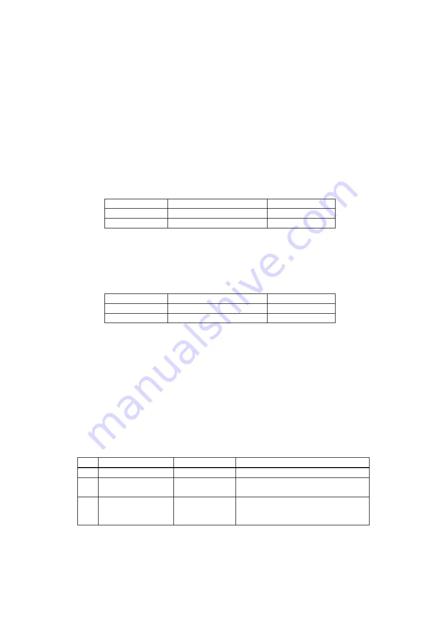
4-3) Command Prompt screen appears, type the commands following instruction below to
start the CXDI software. (Press the [Enter] key after typing the command.)
No. Command
Prompt
Command
Note.
1 C:\>
D:
2 D:\>
cd
ccr
“Space” delimiter is required between
“cd” and “ccr”.
3 D:\ccr>
ccrxxxxx
/np
“Space” delimiter is required between
“xxxxx” and “/”.
“xxxxx” is different in version.
4-4) If the message “Sensor not connected” appears at starting of the CXDI application,
click [OK] button, Change to the “Debugging mode” with the keys ([Alt] + [Tab])
using.
Summary of Contents for CXDI-55C
Page 23: ...2 Installation 7 2 CXDI System II assembly package Accessories box Power box ...
Page 115: ...2 Installation Manual 99 2 Power Box Mass 3 7 Kg Unit mm Dimension tolerance 1 Scale 1 N ...
Page 161: ...4a Canon Inc PWB 60 X RAY 1 2 SCHEMATIC DIAGRAM Rev 01 ...
Page 162: ...4b Canon Inc PWB 60 X RAY 2 2 SCHEMATIC DIAGRAM Rev 01 ...


