


2. Installation
- 5 -
2.2 Product Configuration
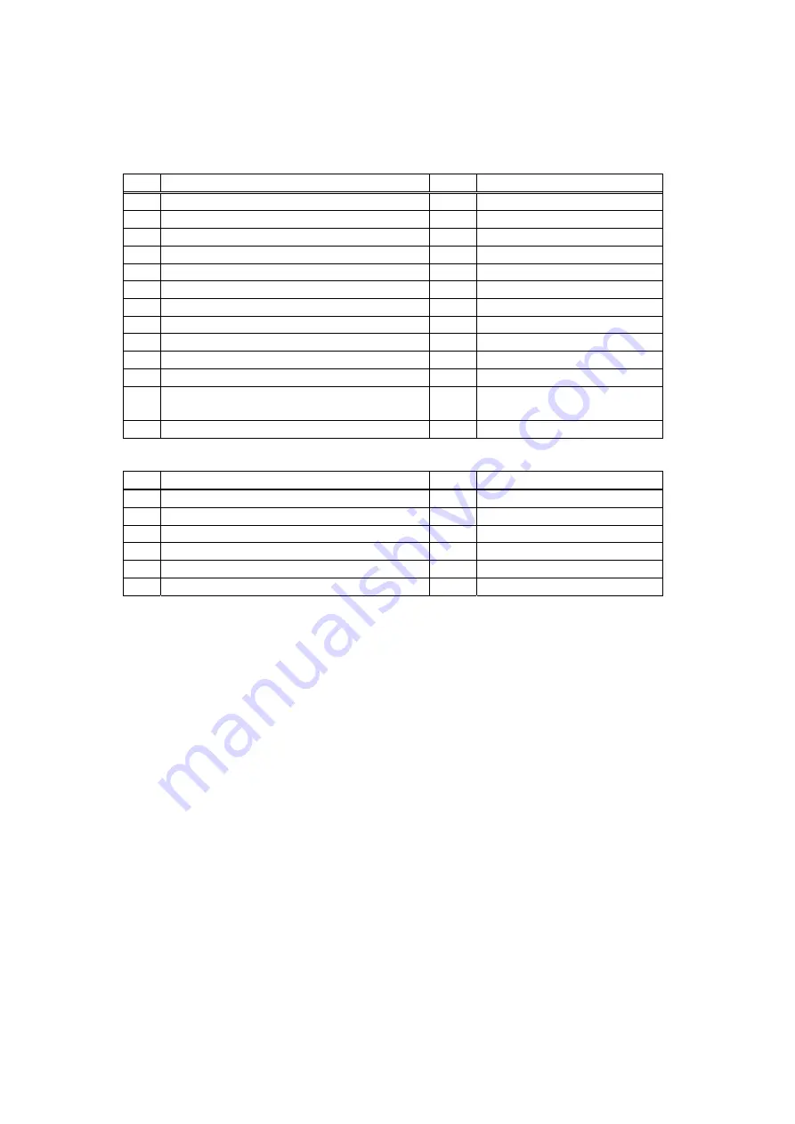
(1) Product Configuration List
1) CXDI-40G COMPACT
No. Item
Name Qty
Remarks
1
CXDI-40G COMPACT Imaging Unit
1
2 Sensor
cable
1 7m
3 Ready
lamp
1
4
Ready lamp mounting shaft
1
5 Insulation
sheet
16
6 Cable
tie
3
7 Screw
(M3x8mm)
4
8
Operation manual (For imaging unit)
-
9
Attached documents for medical
-
(JPN)
10 Warranty
registration
- (JPN)
11 Warranty
card
- (US)
12
Safety Booklet for German (WEEE
directive)
- (EU)
13 Installation
Report
- (US/EU)
2) CXDI SYSTEM III
No. Item
Name Qty
Remarks
1 Power
Box
1
2
X-ray I/F cable
1
20m
3
Power supply cable (with AC plug)
1
3m (100/120/230V)
4 Cable
clamp
1
5 Screw
(M4x6mm)
1
6
Operation manual (Power box)
-
LAN cable for connecting Control PC / Power Box and Network switch (Switching HUB) for
connecting the multiple Imaging Units shall be procured at each sales company.
- LAN cable (Over category 5)
Recommended length of the cable is 30m or less.
When Control PC and Power Box are connected directly, Cross type is used, but when they
are connected via Network switch, Straight type is used. However, this is not applied when
Network switch has AUTO-MDI/MDI-X function*.
- Network switch (Switching HUB)
Sales companies adopt Network switch (Switching HUB) after conducting the test and the
operation check for Switching HUB that meets the general standard.
Summary of Contents for CXDI-40G COMPACT
Page 24: ...2 Installation 4 2 CXDI SYSTEM III Assembly Packaging Accessories Box Power Box ...
Page 56: ...2 Installation 36 8 3 When Timeout due to RX_REQ not Negating ...
Page 135: ...2 Installation 115 16 2 Power Box Mass 4 2 Kg not including cable Unit mm ...
Page 136: ...2 Installation 116 16 3 Ready Lamp Unit Mass 0 5 Kg Unit mm ...


