Chapter 2
2-22
F-2-43
ޓ
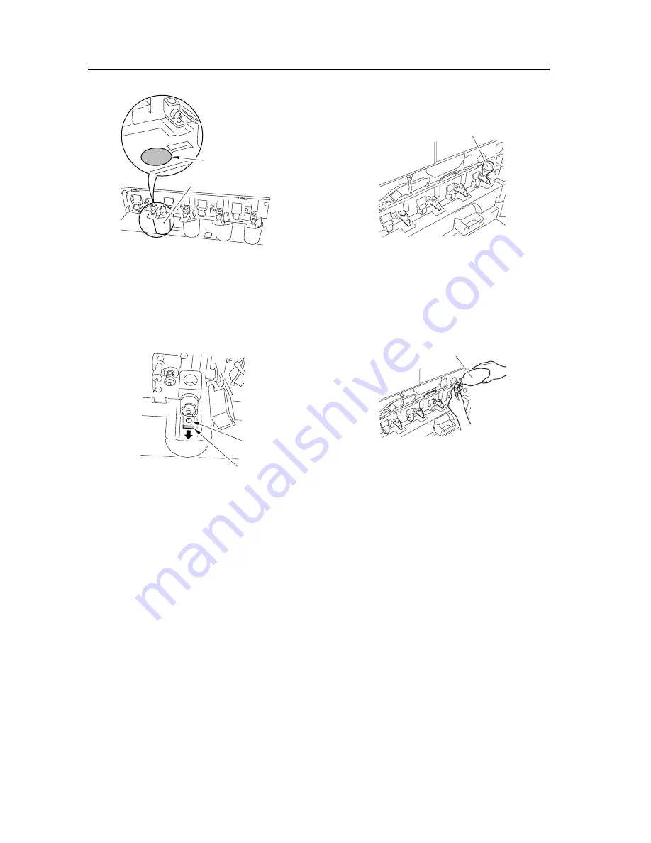
14) Remove the screw [1], and pull out the collecting
container shutter [2]. (At this time, check to make
sure that the collecting container opening is open.)
F-2-44
15) Select the 2nd screen of 'FUNC > INSTALL' in
service mode.
16) To collect all four developers, press 'RECV4'; for
each, press 'RECVC, M, Y, K'. (The developer
will be discharged into the collecting container; the
operation will stop in about 2 min.)
17) When done, close the collecting container shutter,
and fit and tighten the screw.
18) Remove the collecting container.
19) Close the transfer unit.
20) Press 'SPLYC, M, Y, K' as appropriate for the
color to replace on the service mode screen [1].
21) Check to make sure that the screw inside the
developing assembly has started to rotate.
22) Fit the funnel [1] that comes with the starter in the
supply mouth of the developing assembly.
F-2-45
23) Pour developer [1] into the developing assembly.
Tilt the container while turning it to avoid spilling
the developer.
F-2-46
24) When done, press the Stop key to stop the
operation of the developing assembly.
25) Install the hopper metal fixings (left, right), and
release the locking mechanism of the hopper
assembly; then, lower the hopper as far as the metal
fixings.
26) Remove the laser shutter opening tool.
27) Lift the hopper assembly to the topmost position.
(At this time, the locking mechanism will not work;
lock it by hand.)
28) Clean the SALT sensor of the color in question.
29) Remove the hopper retaining fixing (left, right).
30) Release the hopper assembly, and move it down to
its specific position.
31) Select the 1st screen of 'FUNC > INSTALL' in
service mode.
[1]
[2]
[1]
[2]
[1]
[1]
Summary of Contents for CLC5100 Series
Page 1: ...Jul 7 2004 Portable Manual CLC5100 Series ...
Page 2: ......
Page 6: ......
Page 11: ...Chapter 1 Maintenance and Inspection ...
Page 12: ......
Page 14: ......
Page 49: ...Chapter 2 Standards and Adjustments ...
Page 50: ......
Page 77: ...Chapter 2 2 25 F 2 48 5 Tighten the screw 2 for the guide plate View 3 A 2 1 View ...
Page 95: ...Chapter 3 Error Code ...
Page 96: ......
Page 97: ...Contents Contents 3 1 Error Code Details 3 1 3 1 1 Error Code Details 3 1 ...
Page 98: ......
Page 121: ...Chapter 4 User Mode Items ...
Page 122: ......
Page 123: ...Contents Contents 4 1 List of User Modes 4 1 ...
Page 124: ......
Page 127: ...Chapter 5 Service Mode ...
Page 128: ......
Page 130: ......
Page 223: ...Chapter 6 Outline of Components ...
Page 224: ......
Page 226: ......
Page 264: ...Chapter 6 ޓ 6 38 ...
Page 265: ...Chapter 7 System Construction ...
Page 266: ......
Page 268: ......
Page 282: ...Chapter 7 ޓ 7 14 ...
Page 283: ...Chapter 8 Upgrading ...
Page 284: ......
Page 285: ...Contents Contents 8 1 Outline of the Version Upgrade 8 1 ...
Page 286: ......
Page 288: ......
Page 289: ...Jul 7 2004 ...
Page 290: ......


