7-6
FRX4000/FRX6000 4.0 User Guide, Rev 01
Configuring Bandwidth Allocation Groups
To optimize frame relay bandwidth use, various types of interfaces can be assigned to
one of sixteen Bandwidth Allocation Groups, each defined by the parameters listed in
Table 7-1
. Bandwidth Allocation Groups can ensure that response time-sensitive
traffic gets access to the available frame relay bandwidth.
Each of the following entities that use a frame relay port can be assigned (in the
database records) to a Bandwidth Allocation Group:
●
Node (for use in sessions with a NetView host)
●
Logical port
●
SNA Port (LLC2 parameters)
●
IP interface
●
IPX interface
●
LLC2 host
●
LLC2 interface
●
Bridge port
For further control, bandwidth allocation can be enabled or disabled on each frame
relay port.
This feature is applied only when a line's available bandwidth is limited
(i.e., packets must be queued before transmission).
Also note that bandwidth allocation is not applied in a frame relay
passthrough configuration (frame relay PVCs into and out of the FRX
node, internal PVC between the two frame relay ports). (Although the
FRX4000 and FRX6000 support bandwidth allocation, routers and FRADs
that initiate frame relay passthrough do not.)
Be sure you fully understand the needs of the users of the node
before assigning allocation groups; this feature can show adverse
effects if configured incorrectly.
Be sure to configure the same
DLCI rate control
(see page 7-12)
and bandwidth allocation values at both ends of a connection
between Cabletron frame relay access devices. The parameters
should be configured to handle the heavier traffic volume.
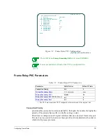
To configure a Bandwidth Allocation Group, press
[H]
at the Node Configuration
Menu (or
[A], [A], [H]
from the Main Menu). A screen similar to the following will be
displayed.
Summary of Contents for Netlink FRX4000
Page 2: ......
Page 16: ...xiv FRX4000 FRX6000 4 0 User Guide Rev 01 ...
Page 17: ...Section I Getting Started ...
Page 18: ......
Page 24: ......
Page 37: ...Section II Configuration ...
Page 38: ......
Page 52: ......
Page 78: ......
Page 106: ...7 24 FRX4000 FRX6000 4 0 User Guide Rev 01 ...
Page 142: ...8 36 FRX4000 FRX6000 4 0 User Guide Rev 01 ...
Page 186: ......
Page 216: ......
Page 266: ......
Page 273: ...Section III Operation ...
Page 274: ......
Page 296: ......
Page 324: ......
Page 376: ......
Page 377: ...Section IV Appendices ...
Page 378: ......
Page 384: ......
Page 390: ......
Page 396: ......
Page 400: ......
Page 405: ...Menu Structure E 5 ...
Page 406: ...E 6 FRX4000 FRX6000 4 0 User Guide Rev 01 ...
Page 425: ......
Page 426: ......


