12-12
FRX4000/FRX6000 4.0 User Guide, Rev 01
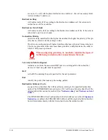
Default Calling Address
will be inserted into an incoming X.29 Call Request if the packet does not contain a
calling address. This parameter is relevant only if
Disable X.121 User Calls
is
N
.
Disable X.121 User Calls
will (if
Y
) cause the port to accept only those calls that substitute an abbreviated
address (described later in this chapter) for the called address.
Autocall
causes (when enabled) the PAD to automatically call the remote device (Called
Address) when the link comes up, either through rebooting the node or pressing
[F7]
after changing
Autocall
to
Y
.
Autocall Delay
causes a delay after the link comes up before a Call Request will be issued.
Called Address
is the ID of the remote device, and is placed into the called address field of the Call
Request. This parameter is relevant only if
Autocall
is
Y
; if
Autocall
is
N
, the called
address will come from either the user device’s X.28 interface or an abbreviated
address.
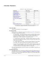
If the async port is one end of a connection to a logical X.25 port in the FRX4000/
6000, the Called Address must match a Subscriber ID (see
page 12-15
) configured for
the logical port.
Retry Count
is the number of times an autocall will be sent to the remote device.
Retry Interval
is the time between autocall attempts.
User Data
is an (optional) string of ASCII characters that will be placed verbatim into the user
data field of an outgoing Call Request packet.
Facilities
is an (optional) string of facility codes and related data that will be placed verbatim
into the facility field of an outgoing Call Request packet.
DTR/RTS Active When VC Up
if
Y
means that DTR and RTS will be asserted only after a virtual circuit is established.
If
N
, both signals will be asserted as soon as the port is enabled.
Input Signal Detection
determines which signal(s) will be read to determine that the link is up:
0
= none required
1
= DSR
2
= DSR & DCD
3
= DSR & DCD & Call
4
= DSR & CTS
5
= DSR, DCD, & CTS
Summary of Contents for Netlink FRX4000
Page 2: ......
Page 16: ...xiv FRX4000 FRX6000 4 0 User Guide Rev 01 ...
Page 17: ...Section I Getting Started ...
Page 18: ......
Page 24: ......
Page 37: ...Section II Configuration ...
Page 38: ......
Page 52: ......
Page 78: ......
Page 106: ...7 24 FRX4000 FRX6000 4 0 User Guide Rev 01 ...
Page 142: ...8 36 FRX4000 FRX6000 4 0 User Guide Rev 01 ...
Page 186: ......
Page 216: ......
Page 266: ......
Page 273: ...Section III Operation ...
Page 274: ......
Page 296: ......
Page 324: ......
Page 376: ......
Page 377: ...Section IV Appendices ...
Page 378: ......
Page 384: ......
Page 390: ......
Page 396: ......
Page 400: ......
Page 405: ...Menu Structure E 5 ...
Page 406: ...E 6 FRX4000 FRX6000 4 0 User Guide Rev 01 ...
Page 425: ......
Page 426: ......


