B-2
FRX4000/FRX6000 4.0 User Guide, Rev 01
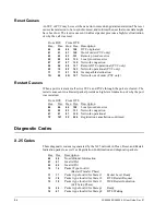
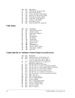
Reset Causes
An SVC or PVC may be reset when an error occurs during data transmission. The reset
causes transmission to be re-synchronized, and informs the user that some data might
have been lost. The reset cause sent in a Reset packet provides a high-level indication
of why the call was reset.
From DCE
From DTE
Hex.
Dec.
Hex. Dec. Description
00
00
80
128
DTE originated
01
01
81
129
Out of order (PVC only)
03
03
83
131
Remote procedure error
05
05
85
133
Local procedure error
07
07
87
135
Network congestion
09
09
89
137
Remote DTE operational (PVC only)
0F
15
8F
143
Network operational (PVC only)
11
17
91
145
Incompatible destination
1D
29
9D
157
Network out of order (PVC only)
Restart Causes
When a port is restarted, all active SVCs and PVCs through the port are cleared. The
restart cause sent in a Restart packet provides a high-level indication of why the port
was restarted.
From DCE
From DTE
Hex.
Dec.
Hex. Dec. Description
00
00
80
128
Local procedure error
03
03
83
131
Network congestion
07
07
87
135
Network operational
7F
127
FF
255
Registration/cancellation confirmed
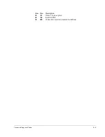
Diagnostic Codes
X.25 Codes
These diagnostic codes are generated by the X.25 network in Clear, Reset, and Restart
Indication packets, as well as Registration Confirmation and diagnostic packets:
Hex. Dec.
Description
00
00
No additional Information
01
01
Invalid P(s)
02
02
Invalid P(r)
10
16
Packet Type Invalid
(Restart Transfer Phase)
11
17
Packet type Invalid for State r1
Packet Level Ready
12
18
Packet type Invalid for State r2
DTE Restart Request
13
19
Packet type Invalid for State r3
DCE Restart Indication
(Call Setup Phase)
14
20
Packet type Invalid for State p1
Ready
15
21
Packet type Invalid for State p2
DTE Waiting
Summary of Contents for Netlink FRX4000
Page 2: ......
Page 16: ...xiv FRX4000 FRX6000 4 0 User Guide Rev 01 ...
Page 17: ...Section I Getting Started ...
Page 18: ......
Page 24: ......
Page 37: ...Section II Configuration ...
Page 38: ......
Page 52: ......
Page 78: ......
Page 106: ...7 24 FRX4000 FRX6000 4 0 User Guide Rev 01 ...
Page 142: ...8 36 FRX4000 FRX6000 4 0 User Guide Rev 01 ...
Page 186: ......
Page 216: ......
Page 266: ......
Page 273: ...Section III Operation ...
Page 274: ......
Page 296: ......
Page 324: ......
Page 376: ......
Page 377: ...Section IV Appendices ...
Page 378: ......
Page 384: ......
Page 390: ......
Page 396: ......
Page 400: ......
Page 405: ...Menu Structure E 5 ...
Page 406: ...E 6 FRX4000 FRX6000 4 0 User Guide Rev 01 ...
Page 425: ......
Page 426: ......


