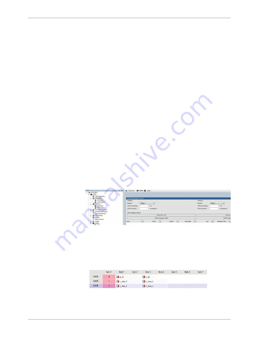
CAN Bus
DDU 8 has two fully configurable CAN buses.
▪ Baudrate (125 kBit to 1 MBit)
▪ 11 Bit or 29 Bit identifiers
▪ Input configuration: Read messages from CAN bus and convert to DDU 8
measurement/display variables. CAN bus supports row counter configura‐
tion.
▪ Output configuration: Write DDU 8 measurement variables to CAN messages,
output frequency and row counter are configurable, CAN gateway function‐
ality (transfer from one bus to the other)
CAN bus trivia
CAN message
▪ 11 Bit (standard) or 29 Bit (extended) identifier
▪ Up to 8 bytes of data payload
CAN bus
▪ Needs termination resistors (120 Ohm) in wiring harness
▪ All devices connected to the bus must use identical data rate
Configuration of DDU 8 bus data rate by double click on the CAN
bus in project tree (1 MBaud, 500 kBit, 250 kBit, 125 kBit)
Row counter concept
▪ Re‐use (multiplex) of message identifiers
▪ One byte of message contains row counter
▪ 7 bytes payload remaining
▪ Position of row counter is configurable
Payload Area
Row
Counter
Row
Counter
Payload Area
Message
Id
9
9.1
9 | CAN Bus
58 / 160
DDU 8 Manual
Bosch Motorsport


