WWW.BIGASSFANS.COM ©2013 DELTA T LLC ALL RIGHTS RESERVED
32
10 - Fan Remote Operator Station (Optional)
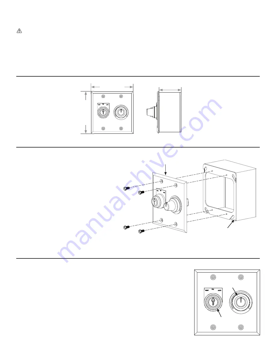
The remote operator station consists of a mode selection knob and a speed control knob.
Use the provided key to turn the mode selection knob.
To prevent unauthorized access to
the remote operator station, do not leave the key in the mode selection knob!
To control the fan automatically
, turn the mode selection knob to the AUTO position.
To start the fan locally
, turn the mode selection knob to the MANUAL position.
To stop the fan locally
and lock it out, turn the mode selection knob to the OFF position.
To adjust fan speed locally
, make sure the mode selection knob is turned to the MANUAL
position, and then rotate the speed control knob to the desired speed setting.
WARNING: Ensure power is disconnected from the fan(s) prior to installing the remote operator station(s).
The remote operator station lets you switch between automated fan control and local fan control. One remote operator station is
required for each fan you plan to control locally. Each remote operator station must be wired to the fan it will control and can be
mounted up to 100 ft (30.5 m) from the fan's VFD. The following pages describe how to mount and operate the remote operator station
and how to wire it to each supported type of VFD.
Note: The required 6-conductor (20AWG minimum) cable is not provided. Big Ass
Fans recommends Belden 5504UE or similarly rated cable.
10.1 - Dimensions
To mount the remote operator station:
1.
Select a flat mounting location from which the fan
is visible and that is 100 ft (30.5 m) or less from
the fan's VFD. The mounting location should also
be readily accessible, free from vibration, and
at an adequate distance from foreign objects or
moving equipment.
2.
Remove the cover and four (4) screws and set
them aside in a safe location.
3.
Route power to the mounting location and mount
the back of the remote operator station (junction
box) to the wall using suitable customer-supplied
mounting screws.
4. Wire the remote operator station to the fan's VFD.
Refer to the following pages for wiring diagrams.
5. Reattach the cover using the four (4) screws as
shown on the right.
4” (102 mm)
4” (102 mm)
1.5” (38 mm)
Mode Selection
Knob
Speed
Control
Knob
10.3 - Operation
10.2 - Installation
Remote Operator Station
(Junction Box)
Cover


