Internal Battery Replacement
237
6.
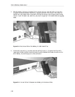
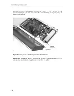
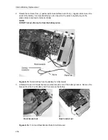
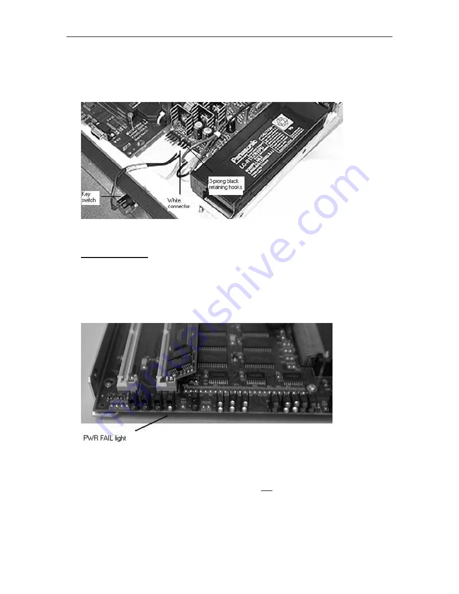
Gently reconnect the white connector to the 3-prong connector for the key switch. (The
white connector’s angular protrusion (crest) will clip under the black retaining hooks).
Figure E-19. Connect 3-Prong Connector for ASG Guard
VERY IMPORTANT! White connector MUST have angular protrusion (crest) on top,
before connecting to prong. An incorrect connection will result in permanent damage
to the Access Security Gateway (ASG) Guard device.
7.
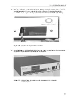
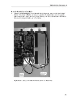
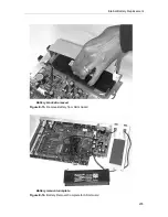
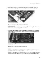
To test the battery connection, re-insert the key and turn the key switch to the ON position.
Observe whether or not the red PWR FAIL light is ON (this light indicates that the internal
battery is operable).
Figure E-20. Test Battery Connection for ASG Guard
NOTE:
If the Access Security Gateway (ASG) Guard does not Power-up (no lights appear on
panel), check and re-secure all connections.
If the Access Security Gateway (ASG) Guard does Power-up (the red PWR FAIL light is
ON, indicating that the internal battery is operable), proceed with the following steps.
Summary of Contents for Lucent Technologies Access Security Gateway Guard
Page 12: ...x Page intentionally left blank ...
Page 28: ...ASG Guard Overview 16 Page intentionally left blank ...
Page 36: ...Physical Connections 24 Page intentionally left blank ...
Page 60: ...Modem Port Setup 48 Page intentionally left blank ...
Page 82: ...Modifying the User Database 70 Page intentionally left blank ...
Page 120: ...Action and Event Tables 108 Page intentionally left blank ...
Page 158: ...User Connectivity 146 Page intentionally left blank ...
Page 188: ...Log Functions 176 Page intentionally left blank ...
Page 236: ...Troubleshooting 224 Page intentionally left blank ...
Page 252: ...Internal Battery Replacement 240 Page intentionally left blank ...
Page 258: ...Glossary of Command References 246 Page intentionally left blank ...


