26
AT40K Series Configuration
1009B–FPGA–03/02
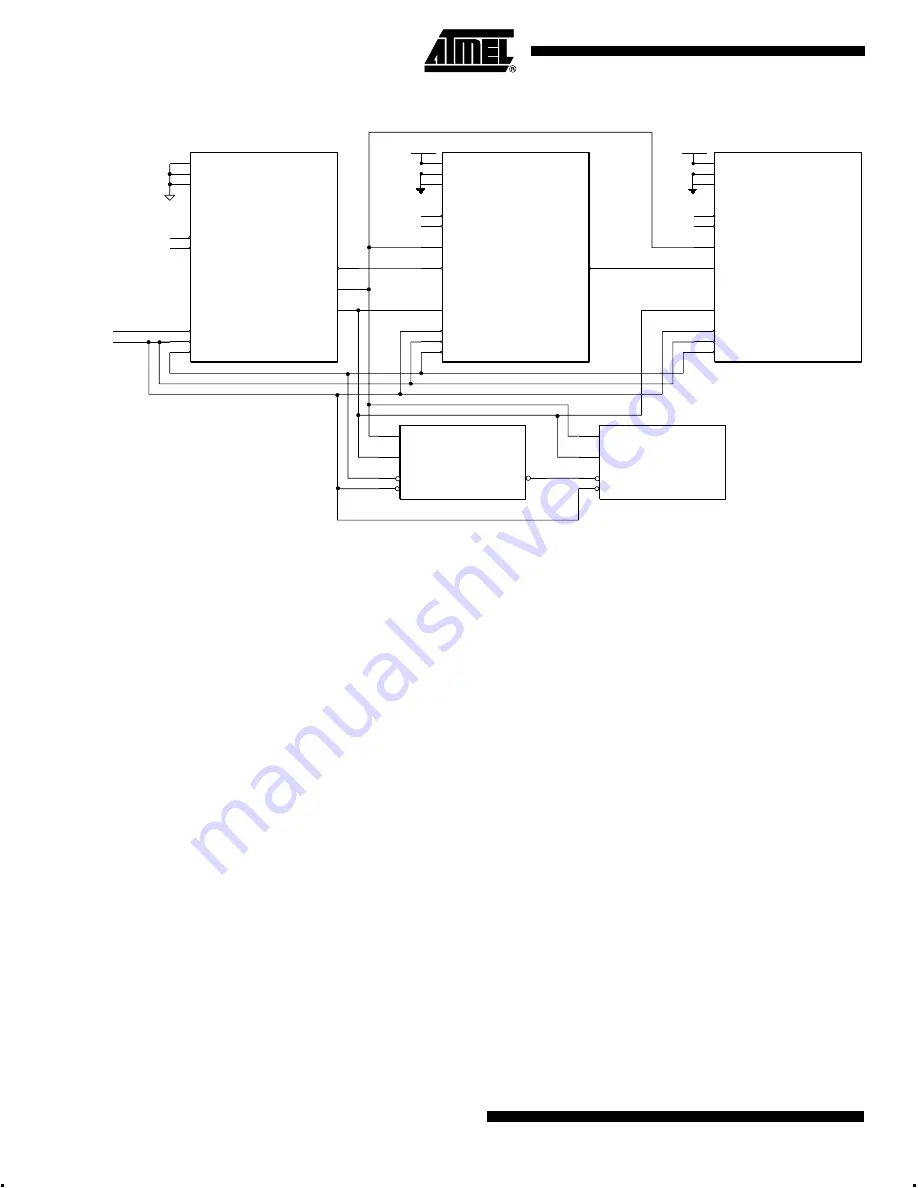
Figure 11.
Cascade 0 11 Configurator System Application
In Mode 1, CCLK is driven by an external device, most often either a microprocessor or
a Master Serial FPGA, in cascade mode. Like the Master Serial device, serial data is
driven into the D
0
pin of the FPGA. To begin configuration, CON must be driven Low.
Once the bitstream is completed, CON is released by the FPGA, indicating the device is
completely ready for user operation. Configuration time depends on the frequency of the
external clock driving CCLK. The maximum frequency in which a Mode 1 device can be
downloaded is 33 MHz. A full bitstream for the AT40K20 can be downloaded in only 4.6
ms (30 ns per bit of configuration data).
Note that all D
0
inputs for the FPGAs in the cascade chain are tied in parallel. The Mas-
ter Serial device does not accept data intended for downstream devices and propagate
it to the next device; instead, it simply passes a chip select downstream. Note that
CSOUT of the upstream Master Serial device is connected to the CS
0
of the down-
stream device.
CS
0
is a dual-use I/O pin is required as a chip select to enable the part to claim the con-
figuration, so care must be taken by the user not to use the CS
0
pin in such a manner
that the part may not be reconfigured. As an example, if the user programs CS
0
as an
output driving High, then CS
0
cannot be lowered, and the part will never reconfigure
without first either powering down or manually resetting. It is recommended therefore
that for Slave Serial Mode, the user leave CS
0
as an input.
Figure 12 shows the timing of the configuration interface after manually initiating a con-
figuration download from the idle state (without reset). Figure 13 shows the timing of the
configuration interface at the end of configuration download. Figure 14 shows the timing
of the configuration interface at the interface of the upstream and downstream devices
in the cascade chain. Table 12 shows the configuration timing parameters pertaining to
these timing diagrams.
M0
M1
M2
OTS
CHECK
CCLK
D<0>
RESET
INIT
CON
CSOUT
AT40K
Mode 0
Master Serial
M0
M1
M2
OTS
CHECK
CCLK
CS
0
D<0>
RESET
INIT
CON
AT40K
Mode 1
VDD
Optional IO
Optional IO
M0
M1
M2
OTS
CHECK
CCLK
D<0>
RESET
INIT
CON
AT40K
Mode 1
VDD
Optional IO
Optional IO
CLK
DATA
CE
RESET
AT17C65
CLK
DATA
CE
RESET
CEO
AT17C010
VSS
RESET
INIT
Optional IO
Optional IO
CSOUT
CS
0


