SERVICE AND SETTING UP
2
- 17
Pegaso 650 I.E.
◆
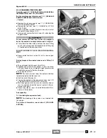
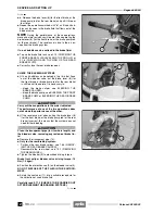
Turn the engine stop switch to position “
2
”.
NOTE
The "workshop mode" interrupts the operation
of the injection system, the coil and the fuel pump for
safety reasons.
◆
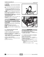
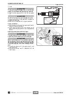
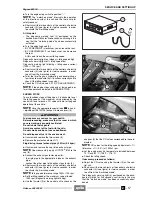
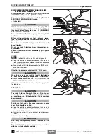
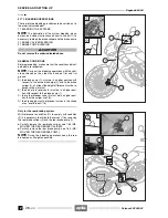
Short-circuit the two contacts of the central unit electric
connector (3) (see figure) for twelve seconds, in order
to activate the "workshop mode".
At this point:
– The diagnostic warning light (4) positioned on the
dashboard will blink for five seconds, confirming in this
way that the "workshop mode" has been successfully
activated.
◆
Turn the adjusting knob (2).
– BY SCREWING IT (clockwise), you increase the rpm;
– BY UNSCREWING IT (anticlockwise), you decrease
the rpm;
At this point reach the correct idling speed.
Diagnostic warning light on (steady) = idling speed high
Diagnostic warning light off = idling speed low
Diagnostic warning light blinking = idling speed correct
[1350 +/- 100 rpm]
◆
Short-circuit the two contacts of the central unit electric
connector (3) (see figure) for twelve seconds, in order
to exit from the "workshop mode".
◆
Twist the throttle grip, accelerating and decelerating a
few times to make sure that it functions correctly and to
check if the idling speed is constant.
◆
Check the CO value, see 4.9.10 (CO ADJUSTMENT).
NOTE
If the engine stops suddenly at low speed, per-
form the operations indicated in SUDDEN STOPS.
SUDDEN STOPS
To avoid sudden stops of the engine, it is advisable to set
the idling speed at the maximum value allowed by the
central unit and to reach a CO value suitable for the good
operation of the vehicle.
NOTE
Have the appropriate special tools
m
to hand:
–
aprilia
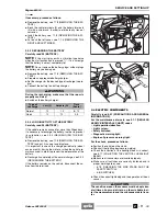
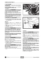
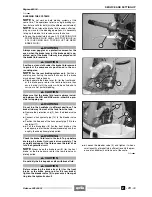
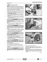
part# 8140196 (exhaust fume analyser) (5).
a
WARNING
Fuel vapours are noxious for your health.
Before proceeding, make sure that the room in which
you are working is properly ventilated.
Do not inhale fuel vapours.
Avoid any contact of the fuel with the skin.
Do not smoke and do not use naked flames.
Do not dispose of fuel in the environment.
◆
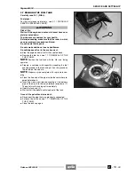
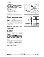
Unscrew and remove the two screws (6).
◆
Remove the protection element (7).
Plug driving torque (exhaust pipe): 25 Nm (2.5 kgm).
◆
Unscrew and remove the cap (8) on exhaust pipe.
NOTE
Upon reassembly, apply LOCTITE
®
8150 to the
cap (8).
◆
Connect the exhaust gas tester pipes (8):
– the rigid pipe to the appropriate intake on the exhaust
pipe;
– connect the other pipe to the exhaust gas tester (5).
◆
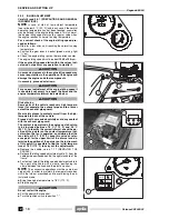
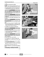
Short-circuit the two contacts of the central unit electric
connector (3) (see figure) for twelve seconds, in order
to activate the "workshop mode".
NOTE
Idling speed tolerance range 1350+/-100 rpm.
◆
Set the idling speed at the maximum value allowed:
– 1450 rpm (diagnostic warning light blinking).
◆
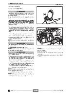
Use the trimmer (9) of the central unit to check on the
Release 00/2002-02
analyzer (5) that the CO values correspond to those in-
dicated.
NOTE
CO values for the idling speed adjustment = 1%
(tolerance: +1%,-0.5%) at 1350±1 rpm.
◆
Let the engine reach a temperature included between
70 °C and 80 °C (158 °F – 176 °F)
◆
Check the idling speed.
If necessary, proceed as follows:
◆
Adjust the CO value using the trimmer (9) on the cen-
tral unit.
◆
Short-circuit the two contacts of the central unit electric
connector (3) (see figure) for twelve seconds, in order
to exit from the "workshop mode".
The diagnostic warning light (4) positioned on the dash-
board will blink for five seconds, confirming in this way
that the "workshop mode" has been successfully aban-
doned.
Summary of Contents for Pegaso 650 I.E.
Page 11: ...1 1 Pegaso 650 I E GENERAL INFORMATION 1 Release 00 2002 02 00 ...
Page 24: ...GENERAL INFORMATION 1 14 Pegaso 650 I E 1 7 2 GENERIC TOOLS Release 00 2002 02 00 ...
Page 39: ...2 1 Pegaso 650 I E 1 SERVICE AND SETTING UP 2 Release 00 2002 02 00 ...
Page 45: ...SERVICE AND SETTING UP 2 7 Pegaso 650 I E LUBRICATION CHART Release 00 2002 02 00 ...
Page 95: ...3 1 Pegaso 650 I E 1 3 ENGINE 3 Release 00 2002 02 00 ...
Page 99: ...ENGINE 3 5 Pegaso 650 I E Release 00 2002 02 00 ...
Page 113: ...4 1 Pegaso 650 I E 1 2 3 FUEL SUPPLY SYSTEM 4 Release 00 2002 02 00 ...
Page 139: ...5 1 Pegaso 650 I E 1 2 3 4 COOLING SYSTEM 5 Release 00 2002 02 00 ...
Page 149: ...6 1 Pegaso 650 I E 1 2 3 4 5 ELECTRIC SYSTEM 6 Release 00 2002 02 00 ...
Page 152: ...6 4 ELECTRIC SYSTEM Pegaso 650 I E 42 0 43 9 54 00 Release 00 2002 02 ...
Page 190: ...ELECTRIC SYSTEM 6 42 Pegaso 650 I E 7 2 2 Release 00 2002 02 00 ...
Page 193: ...7 1 Pegaso 650 I E 1 2 3 4 5 6 CHASSIS 7 Release 00 2002 02 00 ...
Page 287: ...1 2 3 4 5 6 7 8 1 Pegaso 650 I E 1 2 3 4 5 6 7 REPAIR INFORMATION 8 Release 00 2002 02 00 ...
Page 297: ...REPAIR INFORMATION 8 11 Pegaso 650 I E 8 2 3 FUEL SYSTEM PIPES Release 00 2002 02 00 ...
Page 298: ...REPAIR INFORMATION 8 12 Pegaso 650 I E 8 2 4 ENGINE OIL PIPES Release 00 2002 02 00 ...
Page 304: ...REPAIR INFORMATION 8 18 Pegaso 650 I E Release 00 2002 02 00 ...
Page 305: ...Pegaso 650 I E REPAIR INFORMATION 8 19 Release 00 2002 02 00 ...
Page 306: ...REPAIR INFORMATION 8 20 Pegaso 650 I E Release 00 2002 02 00 ...
Page 307: ...REPAIR INFORMATION 8 21 Pegaso 650 I E Release 00 2002 02 00 ...
Page 311: ... 1 Pegaso 650 I E ANALYTICAL INDEX 00 Release 00 2002 02 ...
Page 317: ...ANALYTICAL INDEX 7 Pegaso 650 I E 9 2IF 0AGE 2IF 0AGE 00 Release 00 2002 02 ...


