


CHASSIS
7
- 92
Pegaso 650 I.E.
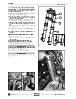
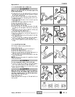
7.11.2 BREAKING THE CHAIN
Carefully read 0.5.1 (PRECAUTIONS AND GENERAL
INFORMATIONS) and 2.29 (DRIVE CHAIN).
◆
Remove the pinion protection case, see 3.2.3 (RE-
MOVING THE DRIVE PINION PROTECTION CAS-
ING).
◆
Slacken the chain, see 2.29.3 (ADJUSTING THE
DRIVING CHAIN).
◆
Position the vehicle on the appropriate rear support
stand, see 1.8.1 (POSITIONING THE VEHICLE ON
THE REAR SUPPORT STAND
m
).
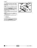
NOTE
Make sure the tool is suitable for the chain type
fitted on the vehicle and for the size of the chain’s links.
◆
Place the rivet tool (1) on the chain at a point between
the sprocket and pinion, on the chain’s lower course.
◆
Move the rivet tool (1) so that its pin exit hole (the one
in the centre) is lined up with the pin on the chain to be
pushed out.
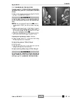
◆
Insert the pusher (2) on the main body (3), with the part
featuring the greatest diameter first.
◆
Fit the main body (3) on the rivet tool (1).
◆
Move the main body (3) so that the locating dowel (4) is
in line with mark “A” on the rivet tool (1).
◆
Turn the screw (5) by hand until the pusher (2) touches
the pin to be pushed out.
NOTE
Make sure the pusher (2) is perfectly in line with
the pin to be pushed out.
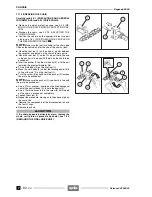
◆
Use a 27 mm spanner, inserted on the fixed hexagonal
seat of the central body (3), to hold the body still.
◆
Use a 19 mm spanner to turn the screw (5) until the pin
on the chain is pushed out completely.
◆
Loosen the screw (5).
◆
Repeat the procedure, moving on to the adjacent pin on
the same link.
◆
Remove the components of the disconnected link and
the four O-rings.
◆
Remove the chain.
a
CAUTION
If the chain appears particularly worn, replace the
whole unit (pinion, sprocket and chain), see 7.3.2
(REMOVING THE FINAL DRIVE UNIT).
Release 00/2002-02
- 00
Summary of Contents for Pegaso 650 I.E.
Page 11: ...1 1 Pegaso 650 I E GENERAL INFORMATION 1 Release 00 2002 02 00 ...
Page 24: ...GENERAL INFORMATION 1 14 Pegaso 650 I E 1 7 2 GENERIC TOOLS Release 00 2002 02 00 ...
Page 39: ...2 1 Pegaso 650 I E 1 SERVICE AND SETTING UP 2 Release 00 2002 02 00 ...
Page 45: ...SERVICE AND SETTING UP 2 7 Pegaso 650 I E LUBRICATION CHART Release 00 2002 02 00 ...
Page 95: ...3 1 Pegaso 650 I E 1 3 ENGINE 3 Release 00 2002 02 00 ...
Page 99: ...ENGINE 3 5 Pegaso 650 I E Release 00 2002 02 00 ...
Page 113: ...4 1 Pegaso 650 I E 1 2 3 FUEL SUPPLY SYSTEM 4 Release 00 2002 02 00 ...
Page 139: ...5 1 Pegaso 650 I E 1 2 3 4 COOLING SYSTEM 5 Release 00 2002 02 00 ...
Page 149: ...6 1 Pegaso 650 I E 1 2 3 4 5 ELECTRIC SYSTEM 6 Release 00 2002 02 00 ...
Page 152: ...6 4 ELECTRIC SYSTEM Pegaso 650 I E 42 0 43 9 54 00 Release 00 2002 02 ...
Page 190: ...ELECTRIC SYSTEM 6 42 Pegaso 650 I E 7 2 2 Release 00 2002 02 00 ...
Page 193: ...7 1 Pegaso 650 I E 1 2 3 4 5 6 CHASSIS 7 Release 00 2002 02 00 ...
Page 287: ...1 2 3 4 5 6 7 8 1 Pegaso 650 I E 1 2 3 4 5 6 7 REPAIR INFORMATION 8 Release 00 2002 02 00 ...
Page 297: ...REPAIR INFORMATION 8 11 Pegaso 650 I E 8 2 3 FUEL SYSTEM PIPES Release 00 2002 02 00 ...
Page 298: ...REPAIR INFORMATION 8 12 Pegaso 650 I E 8 2 4 ENGINE OIL PIPES Release 00 2002 02 00 ...
Page 304: ...REPAIR INFORMATION 8 18 Pegaso 650 I E Release 00 2002 02 00 ...
Page 305: ...Pegaso 650 I E REPAIR INFORMATION 8 19 Release 00 2002 02 00 ...
Page 306: ...REPAIR INFORMATION 8 20 Pegaso 650 I E Release 00 2002 02 00 ...
Page 307: ...REPAIR INFORMATION 8 21 Pegaso 650 I E Release 00 2002 02 00 ...
Page 311: ... 1 Pegaso 650 I E ANALYTICAL INDEX 00 Release 00 2002 02 ...
Page 317: ...ANALYTICAL INDEX 7 Pegaso 650 I E 9 2IF 0AGE 2IF 0AGE 00 Release 00 2002 02 ...


