COOLING SYSTEM
5
- 8
Pegaso 650 I.E.
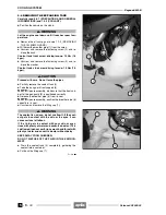
2%-/6).' 4(% %80!.3)/. 4!.+
Carefully read 0.5.1 (PRECAUTIONS AND GENERAL
INFORMATIONS) and 1.2.5 (COOLANT).
◆
Position the vehicle on the stand.
a
WARNING
Let the engine cool down until it reaches room tem-
perature.
◆
Remove the oil sump guard, see 7.1.3 (REMOVING
THE OIL SUMP GUARD).
◆
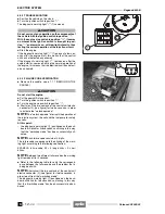
Withdraw the breather pipe (1) from the union.
◆
Unscrew and remove the fastening screw (2) and re-
trieve the bush.
Coolant tank front screw driving torque: 10 Nm (1.0
kgm).
◆
Unscrew and remove the fastening screw (3) and re-
trieve the washer.
Coolant tank side screw driving torque: 10 Nm (1.0
kgm).
a
CAUTION
Proceed with care. Do not force the pipes
◆
Partially remove the coolant tank (4).
◆
Take the pan guard front support (5).
NOTE
Upon reassembly, make sure that the front sup-
port of the pan guard (5) is positioned correctly.
◆
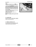
Release the breather pipe (6) from its seat.
NOTE
Upon reassembly, position the breather pipe (6)
correctly in its seat.
◆
Unscrew and remove the filling cap (7).
a
WARNING
The coolant is noxious: do not swallow it; if the cool-
ant gets in contact with the skin or the eyes, it can
cause serious irritations.
If the fluid gets in contact with your skin or eyes,
rinse with plenty of water and consult a doctor. If it is
swallowed, induce vomit, rinse mouth and throat with
plenty of water and consult a doctor without delay.
KEEP AWAY FROM CHILDREN.
DO NOT DISPOSE OF THE FLUID IN THE ENVIRON-
MENT.
◆
Drain the coolant tank (4) completely, gathering the
coolant into a container.
◆
Put back the filling cap (7).
Follow
ã
- 00
Release 00/2002-02
Summary of Contents for Pegaso 650 I.E.
Page 11: ...1 1 Pegaso 650 I E GENERAL INFORMATION 1 Release 00 2002 02 00 ...
Page 24: ...GENERAL INFORMATION 1 14 Pegaso 650 I E 1 7 2 GENERIC TOOLS Release 00 2002 02 00 ...
Page 39: ...2 1 Pegaso 650 I E 1 SERVICE AND SETTING UP 2 Release 00 2002 02 00 ...
Page 45: ...SERVICE AND SETTING UP 2 7 Pegaso 650 I E LUBRICATION CHART Release 00 2002 02 00 ...
Page 95: ...3 1 Pegaso 650 I E 1 3 ENGINE 3 Release 00 2002 02 00 ...
Page 99: ...ENGINE 3 5 Pegaso 650 I E Release 00 2002 02 00 ...
Page 113: ...4 1 Pegaso 650 I E 1 2 3 FUEL SUPPLY SYSTEM 4 Release 00 2002 02 00 ...
Page 139: ...5 1 Pegaso 650 I E 1 2 3 4 COOLING SYSTEM 5 Release 00 2002 02 00 ...
Page 149: ...6 1 Pegaso 650 I E 1 2 3 4 5 ELECTRIC SYSTEM 6 Release 00 2002 02 00 ...
Page 152: ...6 4 ELECTRIC SYSTEM Pegaso 650 I E 42 0 43 9 54 00 Release 00 2002 02 ...
Page 190: ...ELECTRIC SYSTEM 6 42 Pegaso 650 I E 7 2 2 Release 00 2002 02 00 ...
Page 193: ...7 1 Pegaso 650 I E 1 2 3 4 5 6 CHASSIS 7 Release 00 2002 02 00 ...
Page 287: ...1 2 3 4 5 6 7 8 1 Pegaso 650 I E 1 2 3 4 5 6 7 REPAIR INFORMATION 8 Release 00 2002 02 00 ...
Page 297: ...REPAIR INFORMATION 8 11 Pegaso 650 I E 8 2 3 FUEL SYSTEM PIPES Release 00 2002 02 00 ...
Page 298: ...REPAIR INFORMATION 8 12 Pegaso 650 I E 8 2 4 ENGINE OIL PIPES Release 00 2002 02 00 ...
Page 304: ...REPAIR INFORMATION 8 18 Pegaso 650 I E Release 00 2002 02 00 ...
Page 305: ...Pegaso 650 I E REPAIR INFORMATION 8 19 Release 00 2002 02 00 ...
Page 306: ...REPAIR INFORMATION 8 20 Pegaso 650 I E Release 00 2002 02 00 ...
Page 307: ...REPAIR INFORMATION 8 21 Pegaso 650 I E Release 00 2002 02 00 ...
Page 311: ... 1 Pegaso 650 I E ANALYTICAL INDEX 00 Release 00 2002 02 ...
Page 317: ...ANALYTICAL INDEX 7 Pegaso 650 I E 9 2IF 0AGE 2IF 0AGE 00 Release 00 2002 02 ...


