background image

ANALYTICAL INDEX


@


- 6

Pegaso 650 I.E.

3

2IF

0AGE

SADDLE LOCK - (REMOVAL)

7.1.30

7-24-00

SADDLE SUPPORT - (REMOVAL)

7.1.36

7-28-00

SEALANTS

3.1.4

3-3-00

SERIAL NUMBERS - (POSITION)

1.1

1-3-00

SERVICE AND REPAIR - (GENERAL 
INFORMATION)

3.1.9

3-3-00

SIDE STAND - (REMOVAL)

7.1.41

7-32-00

SPARE PARTS - (CATALOGUE)

0.4.2

0-6-00

SPARE PARTS - (WARNINGS)

1.4

1-7-00

SPARK PLUG

2.6

2-11-00

SPARK PLUGS (no spark)

8.3.1

8-22-00

SPECIAL TOOLS

1.7

1-12-00

SPECIAL TOOLS - (CATALOGUE)

0.4.3

0-6-00

SPECIFIC TOOLS

1.7.1

1-12-00

SPEEDOMETER-ODOMETER - (CABLE)

8.2.9

8-15-00

SPROCKET, PINION AND CHAIN - 
(CHECKING THE WEAR)

2.29.2

2-48-00

STEERING

7.7

7-70-00

STEERING

2.22

2-39-00

STEERING - (TECHNICAL 
SPECIFICATIONS)

8.4.11

8-23-00

STEERING BEARINGS - 
(ADJUSTMENTING THE SLACK)

2.22.2

2-39-00

STEERING BEARINGS - (CHECKING 
THE SLACK)

2.22.1

2-39-00

STEERING LOCK - (REMOVAL)

7.1.20

7-19-00

STRUCTURE (FRAME-SADDLE 
SUPPORT) - (TECHNICAL 
SPECIFICATIONS)

8.4.13

8-23-00

SUPPLY SYSTEM - (PIPES)

8.2.3

8-11-00

SWITCHES

6.8

6-24-00

SYMBOLS

0.7

0-9-00

4

2IF

0AGE

TANK - (DRAINING THE FUEL)

2.7

2-13-00

TECHNICAL DATA

1.5

1-8-00

TECHNICAL DATA AND 
SPECIFICATIONS

8.4

8-23-00

TECHNICAL INFORMATION

3.1

3-3-00

TECHNICAL SPECIFICATIONS

8.4

8-23-00

TERMINALS AND CLAMPS - (CHECKING 
AND CLEANING)

2.3.2

2-8-00

THERMAL EXPANSION VALVE

5.8

5-9-00

THROTTLE BODY

4.9

4-14-00

THROTTLE BODY - (ADJUSTMENTS)

4.9.8

4-22-00

THROTTLE BODY - (ASSEMBLY)

4.9.6

4-20-00

THROTTLE BODY - (DISASSEMBLY)

4.9.3

4-17-00

THROTTLE BODY - (INSPECTION)

4.9.5

4-19-00

THROTTLE BODY - (REMOVAL)

4.9.2

4-16-00

THROTTLE BODY - (TECHNICAL 
SPECIFICATIONS)

8.4.2

8-23-00

THROTTLE GRIP - (ADJUSTMENT)

2.9.3

2-18-00

THROTTLE GRIP - (CABLE)

8.2.8

8-14-00

THROTTLE GRIP - (REMOVAL)

7.1.17

7-16-00

THROTTLE VALVES - (ADJUSTING THE 
POTENTIOMETER)

4.9.9

4-23-00

TOOLS USED FOR OTHER VEHICLES

1.7.3

1-16-00

TRANSFERS

1.11

1-25-00

TREAD

2.30.1

2-50-00

TYRES

7.4

7-56-00

TYRES

2.30

2-50-00

TYRES - (ASSEMBLY)

7.4.3

7-57-00

TYRES - (DISASSEMBLY)

7.4.1

7-56-00

5

2IF

0AGE

UPDATED MANUAL GENERAL LIST

0.1.2

0-3-00

6

2IF

0AGE

VOLTAGE REGULATOR - (CHECK)

6.3.4

6-7-00

7

2IF

0AGE

WARNINGS

1.2

1-4-00

WHEELS - (TECHNICAL 
SPECIFICATIONS)

8.4.8

8-23-00

WHOLE FINAL DRIVE UNIT - (REMOVAL)

7.3.2

7-45-00

WIRING DIAGRAM

6.19

6-42-00

8

2IF

0AGE

- 00

Release 00/2002-02

Summary of Contents for Pegaso 650 I.E.

Page 1: ... GENERAL INFORMATION 1 SERVICE AND SETTING UP 2 ENGINE 3 FUEL SUPPLY SYSTEM 4 COOLING SYSTEM 5 ELECTRIC SYSTEM 6 CHASSIS 7 REPAIR INFORMATION 8 ANALYTICAL INDEX Release 00 2002 02 00 0EGASO 650 U 1 WORKSHOP manual aprilia part 8140638 ...

Page 2: ... MANUALS 0 6 00 0 4 2 SPARE PARTS CATALOGUES 0 6 00 0 4 3 SPECIAL TOOL MANUALS 0 6 00 0 4 4 USE AND MAINTENANCE MANUALS 0 6 00 3 49 7 2 3 0 7 00 0 5 1 PRECAUTIONS AND GENERAL INFORMATIONS 0 7 00 0 5 2 BEFORE THE DISASSEMBLY OF THE COMPONENTS 0 7 00 0 5 3 DISASSEMBLING THE COMPONENTS 0 7 00 0 5 4 REASSEMBLING THE COMPONENTS 0 7 00 7 4 53 9 52 3 26 2 0 2 5 0 8 00 0 6 1 ADVICE FOR CONSULTATION 0 8 00...

Page 3: ...00 2 50 00 00 2 51 00 00 2 52 00 00 2 53 00 00 2 54 00 00 2 55 00 00 2 56 00 00 3 1 00 00 3 2 00 00 3 3 00 00 3 4 00 00 3 5 00 00 3 6 00 00 3 7 00 00 3 8 00 00 3 9 00 00 3 10 00 00 3 11 00 00 3 12 00 00 3 13 00 00 3 14 00 00 3 15 00 00 3 16 00 00 3 17 00 00 3 18 00 00 4 1 00 00 4 2 00 00 4 3 00 00 4 4 00 00 4 5 00 00 4 6 00 00 4 7 00 00 4 8 00 00 4 9 00 00 4 10 00 00 4 11 00 00 4 12 00 00 4 13 00 ...

Page 4: ... 64 00 00 7 65 00 00 7 66 00 00 7 67 00 00 7 68 00 00 7 69 00 00 7 70 00 00 7 71 00 00 7 72 00 00 7 73 00 00 7 74 00 00 7 75 00 00 7 76 00 00 7 77 00 00 7 78 00 00 7 79 00 00 7 80 00 00 7 81 00 00 7 82 00 00 7 83 00 00 7 84 00 00 7 85 00 00 7 86 00 00 page Release Release 00 2002 02 00 7 87 00 00 7 88 00 00 7 89 00 00 7 90 00 00 7 91 00 00 7 92 00 00 7 93 00 00 7 94 00 00 8 1 00 00 8 2 00 00 8 3 0...

Page 5: ... the Release 5 Section number 6 Section page consecutive number 7 Updated page consecutive number 8 Chapter title numbered consecutively 9 Paragraph title numbered consecutively 10 Description of the operation always preceded by a rhombus 11 Description of the operation the star means that the operation must be repeated on the other side of the vehicle Release 00 2002 02 00 ...

Page 6: ...ll be described in the successi ve editions of this manual In case of need or in case there are any doubts regar ding the repair and servicing procedures contact the aprilia Consumer Service A C S which will give you any information required and will also inform you about any updating and technical modifications of the vehi cle aprilia s p a reserves the right to modify its models at any time with...

Page 7: ...together make sure that each is working in safe conditions Carefully read 1 2 INSTRUCTIONS FOR USE OF FUEL LUBRICANTS COOLANT AND OTHER COM PONENTS 0 5 2 BEFORE THE DISASSEMBLY OF THE COMPONENTS Remove any dirt mud dust and foreign matters from the vehicle before disassembling the components Use when necessary the special tools designed for this vehicle 0 5 3 DISASSEMBLING THE COMPONENTS Do not lo...

Page 8: ...operations in rever se order The terms right and left are referred to the rider sea ted on the vehicle in the normal riding position For normal maintenance operations and for the use of the vehicle consult the USE AND MAINTENANCE manual The operations preceded by this symbol must be repeated on the opposite side of the vehi cle In this manual the various versions are indicated by the following sym...

Page 9: ...International Standardization Organization kg kilograms kgm kilograms per metre 1 kgm 10 Nm km kilometres km h kilometres an hour kΩ kilo ohms kPa kiloPascal 1 kPa 0 01 bar KS clutch side Kupplungseite kW kilowatt L litres LAP lap race course LED Light Emitting Diode LEFT SIDE left side m s metres an second MAX maximum mbar millibar 1mbar 0 1 kPa mi mile MIN minimum MPH miles per hour MS flywheel ...

Page 10: ...NOTE T H I S P A G E H A S B E E N I N T E N T I O N A L L Y L E F T E M P T Y INTRODUCTION 0 10 Pegaso 650 I E Release 00 2002 02 00 ...

Page 11: ...1 1 Pegaso 650 I E GENERAL INFORMATION 1 Release 00 2002 02 00 ...

Page 12: ... 30 2 0 243 1 7 00 4 30 4 3 1 8 00 5 2 4 24 1 11 00 30 4 3 m 1 12 00 1 7 1 SPECIFIC TOOLS 1 12 00 1 7 2 GENERIC TOOLS 1 14 00 1 7 3 TOOLS USED FOR OTHER VEHICLES 1 16 00 0 3 4 4 6 4 3500 24 34 1 17 00 1 8 1 POSITIONING THE VEHICLE ON THE REAR SUPPORT STAND m 1 17 00 1 8 2 POSITIONING THE VEHICLE ON THE FRONT SUPPORT STAND m 1 17 00 35 3 1 18 00 1 9 1 PRODUCT PROPERTIES 1 18 00 34 43 1 19 00 1 10 1...

Page 13: ...o not want to incur severe penal and administrative sanctions In particular the alteration of the frame number results in the immediate invalidity of the guarantee 1 1 1 FRAME NUMBER The frame number is stamped on the right side of the steering column 1 1 2 ENGINE NUMBER The engine number is stamped on the rear part of the en gine near the pinion Release 00 2002 02 00 ...

Page 14: ...rious damage to the skin if handled daily and for long periods Wash your hands carefully after use Do not dispose of the oil in the environment Deliver it to or have it collected by the nearest oil sal vage center or by the supplier In case any maintenance operation has to be carried out it is advisable to use latex gloves For the maintenance intervals see 2 1 1 REGULAR SERVICE INTERVALS CHART und...

Page 15: ...gets in con tact with your skin or eyes rinse with plenty of water and consult a doctor If it is swallowed induce vomit rinse mouth and throat with plenty of water and consult a doctor with out delay DO NOT DISPOSE OF THE FLUID IN THE ENVIRON MENT KEEP AWAY FROM CHILDREN aWARNING Be careful not to spill the coolant on the red hot parts of the engine it may catch fire and send out invisible flames ...

Page 16: ...e in the clutch levers may be due to trouble in the hydraulic circuits Check that the clutch hoses are not twisted or worn Prevent water or dust from accidentally getting into the circuit In case maintenance operations are to be performed on the hydraulic circuit it is advisable to use latex gloves 1 2 7 CARBON MONOXIDE If it is necessary to let the engine run in order to carry out some work make ...

Page 17: ...e brake disc During the first 500 km 312 mi never exceed 4000 rpm see table aCAUTION After the first 2000 km 1250 mi perform the checking operations indicated in the after running in col umn see 2 1 1 REGULAR SERVICE INTERVALS CHART in order to avoid injuring yourself or others a o damaging the vehicle Between the first 1000 km 625 mi and 2000 km 1250 mi drive more briskly change speed and use the...

Page 18: ...ring intake stroke opening during exhaust stroke closing during exhaust stroke 5 before TDC 40 after BDC 47 before TDC 7 after BDC Valve clearance during intake stroke 0 10 0 19 mm Centre inlet valve clearance 0 07 0 10 mm measured between roller and camshaft Valve clearance during exhaust stroke 0 10 0 19 mm Engine revolutions at minimum rpm 1350 100 rpm Ignition SAGEM inductive ignition system S...

Page 19: ...525 dimensions 5 8 x 5 16 FUEL SUPPLY SYSTEM Type electronic injection Choke Ø 34 mm FUEL SUPPLY Type indirect injection MULTIPOINT Fuel Unleaded petrol according to the DIN 51 607 standard min O N 95 N O R M and 85 N O M M FRAME Type composite structure in steel and light alloy with remov able cradle and saddle pillar Steering inclination angle 28 Fore stroke 109 mm SUSPENSIONS Front telescopic a...

Page 20: ...tion pressure rider with passenger off road driving 210 kPa 2 1 bar asphalted road 230 kPa 2 3 bar SPARK PLUGS Standard NGK R DR8EB Spark plug gap 0 6 0 7 mm Resistance 5 kΩ ELECTRIC SYSTEM Battery 12 V 12 Ah Fuses 7 5 A 15 A 20 A Generator with permanent magnet 12 V 400 W BULBS Low beam bulb high beam 12 V 55 60 W High beam 12 V 60 W Front parking light 12 V 3 W Direction indicators 12 V 10 W Rea...

Page 21: ... of the volume SAE 15W 0F A 5W 33 of the volume 0F A 20W 67 of the volume or FORK 5W 33 of the volume FORK 20W 67 of the volume Bearings and other lubrication points recommended 0AUTOGREASE MP or GREASE 30 As an alternative to the recommended product use high quality grease for rolling bearings working temperature range 30 C 140 C dripping point 150 C 230 C high protection against corrosion good r...

Page 22: ...al tools avoids the potential risk of dam age as a result of inappropriate tools and or improvised methods Below is a list of the special tools designed especially for this specific vehicle If necessary request the special tools see aprilia part 8202278 I f d E U aCAUTION Before using the special tools consult any docu ments attached 1 7 1 SPECIFIC TOOLS Release 00 2002 02 00 ...

Page 23: ...rshaft 22 0277227 oil seal pad transmission selector shaft 23 0277270 balance shaft split gear centering pin 24 0277205 extractor for idler gear pin 25 0277302 oil seal pad disengaging shaft 26 0276357 ring compressor 27 0277881 clutch blocking tool 28 0277242 pad with 22 mm piston pin snap ring assembly bush 29 0277240 pad with 24 mm piston pin snap ring assembly bush 30 0277265 extractor for bal...

Page 24: ...GENERAL INFORMATION 1 14 Pegaso 650 I E 1 7 2 GENERIC TOOLS Release 00 2002 02 00 ...

Page 25: ...are part aprilia part 8140196 exhaust fume analyser 16 8140396 tubular screen filter spare part aprilia part 8140196 exhaust fume analyser 17 8140397 oxygen sensor spare part aprilia part 8140196 exhaust fume analyser 18 0297431 LOCTITE Anti Seize 76710 19 0297900 Gasket paste 310 ml 20 0297433 MOLYKOTE G N 50 g 21 0897161 MOLYKOTE 111 22 0297386 SILASTIC 732 RTV 100 g 23 8116067 LOCTITE 8150 for ...

Page 26: ...6 Paste Klueber 60 gr 5 0297434 LOCTITE 767 Anti Seize 15378 6 8116050 engine oil 7 xxxxxxx N A LOCTITE 572 8 8116053 grease v Bimol Grease 481 9 8116038 grease LUBERING ST 10 xxxxxxx N A AP LUBE temporary lubricant 11 xxxxxxx N A DID CHAIN LUBE grease 12 8116031 Biosolvent frame detergent 13 8116945 ACRILON 28 cyanoacrylic glue 14 xxxxxxx N A MOTUL MOTOWASH degreaser 15 xxxxxxx N A Alcohol Releas...

Page 27: ...upport pin 3 rests on the right side against the rear fastening plate of the lower chain guard NOTE Have someone help you keep the vehicle in ver tical position with the two wheels on the ground aWARNING Grasping the stand in another way than indicated in the figure may cause your fingers to be crushed be tween the stand and the ground Grasp the terminal central part of the stand 7 Pos C Push the ...

Page 28: ...ase the part glued it may be necessary to heat the coupled parts to a temperature of 250 C 482 F aprilia part 0899784 LOCTITE 574 orange Solvent free seal in paste to be used instead of seals where there is a high friction factor and where a precise distance is required between the two components Applied in its liquid state it hardens after assembly on contact with the metal within a few hours A s...

Page 29: ...l neces sary for the correct reassembly NOTE Have the appropriate special tool m to hand aprilia part 0277295 hose clamp installation pliers aCAUTION Upon installation replace the hose clamp that has been removed with a new one having the same di mensions see 0 4 2 SPARE PARTS CATALOGUES Do not attempt to reinstall the removed hose clamp since it is unusable Do not replace the removed hose clamp w...

Page 30: ...peat the previous operation by applying the pre scribed driving torque NOTE In this way the pressure exerted by the fasten ing elements will be uniformly distributed on the joint sur face For the maintenance intervals see 2 1 1 REGULAR SERVICE INTERVALS CHART under Nut bolt screw tightening aCAUTION The fastening elements featured in the table must be torqued to specification using a torque spanne...

Page 31: ...de roller 1 M8X50 20 2 0 Connector plate to fairing support frame 1 M5X16 20 2 0 Triangle frame guard 1 M5X12 20 2 0 FOOTRESTS Description Q ty Screw nut Nm kgm Note Left front screw that fastens footboard to engine cradle 1 M10 50 5 0 Engine cradle lower fastening 2 M10 50 5 0 Footrests on support 2 M10X40 80 8 0 Footboard support to saddle pillar 4 M8X25 25 2 5 STAND Description Q ty Screw nut N...

Page 32: ...pe clamps 2 3 9x14 3 0 3 Fastening air filter casing 2 M6x30 6 0 6 Filter case to lower saddle pillar 1 M6x12 7 0 7 Air temperature sensor 1 3 0 3 EXHAUST SYSTEM Description Q ty Screw nut Nm kgm Note Exhaust pipes 4 M8 25 2 5 Left silencer 2 M8X16 25 2 5 Left silencer 1 M8X20 25 2 5 Right silencer 2 M8X16 25 2 5 Right silencer 1 M8X20 25 2 5 Silencer guards 6 M6X16 8 0 8 Silencer exhaust pipe cla...

Page 33: ...m kgm Note Starter relay wiring 2 M6 4 0 4 Horn support 1 M8X20 12 1 2 Voltage regulator 2 M6X20 8 0 8 Central unit to glove compartment 1 M5X25 3 0 3 Direction indicators to front transparent part of the fairing 2 3 9X14 1 5 0 15 Headlight on fairing 2 M4 2X20 2 0 2 2 M5X20 2 0 2 Battery clamping bracket 1 M5X20 3 0 3 LIGHTS DASHBOARD Description Q ty Screw nut Nm kgm Note Fastening to fairing su...

Page 34: ... Luggage rack on saddle support 2 M8X20 12 1 2 Luggage rack on saddle support 1 M8X16 12 1 2 SECURING LOCKS Description Q ty Screw nut Nm kgm Note Fastening of saddle support 2 M6X30 10 1 0 Cap to tank 3 M5X30 5 0 5 Cap to tank 4 M5X1 5 0 5 FRONT MUDGUARD Description Q ty Screw nut Nm kgm Note Mudguard fastening 2 M5X12 7 0 7 Mudguard lower fastening 2 M5X20 5 0 5 Grommet fastening 1 M5X16 1 0 1 R...

Page 35: ...mpletely NOTE It is advisable to use a sprayer 2 When using a sponge dab the surface with the sponge without pressing hard so as to avoid damaging the adhe sive Wet the surface of the adhesive with soapy water Apply the transfer 3 on the surface to be decorated and move it into the right position NOTE Always move the spatula in constant strokes from the centre of the transfer out Using the spatula...

Page 36: ...ion tape 5 from the surface of the transfer In order to assure good adhesion move the spatula over the transfer again concentrating in particular on the edges and corners NOTE With the wet method the final level of the trans fer is reached approx 48 hours after application Once the application tape has been removed make sure there are no air bubbles anywhere on the surface In the event air bubbles...

Page 37: ...GENERAL INFORMATION NOTE 1 27 T H I S P A G E H A S B E E N I N T E N T I O N A L L Y L E F T E M P T Y Pegaso 650 I E Release 00 2002 02 00 ...

Page 38: ...GENERAL INFORMATION NOTE 1 28 T H I S P A G E H A S B E E N I N T E N T I O N A L L Y L E F T E M P T Y Pegaso 650 I E Release 00 2002 02 00 ...

Page 39: ...2 1 Pegaso 650 I E 1 SERVICE AND SETTING UP 2 Release 00 2002 02 00 ...

Page 40: ...DING THE BRAKING SYSTEMS 2 34 00 4 2 4 2 5 2 35 00 4 2 2 2 5 2 36 00 534 4 2 2 2 42 6 2 2 2 37 00 4 2 0 7 2 2 38 00 34 2 2 39 00 2 22 1 CHECKING THE BEARING SLACK STEERING 2 39 00 2 22 2 ADJUSTING THE BEARING SLACK STEERING 2 39 00 2 2 2 2 40 00 2 23 1 ADJUSTING THE REAR FORK 2 40 00 30 4 4 2 4 2 2 3530 3 2 41 00 2 24 1 FRONT SUSPENSION 2 41 00 30 4 4 2 2 3530 3 2 42 00 2 25 1 REAR SUSPENSION 2 42...

Page 41: ...d Before proceeding make sure that the room in which you are working is properly ventilated Keep away from the red hot parts of the engine and of the exhaust system in order to avoid burns If not expressly indicated otherwise for the reassem bly of the units repeat the disassembly operations in reverse order In case any maintenance operation should be re quired it is advisable to use latex gloves ...

Page 42: ...5 mi Every 6000 km 3750 mi or 12 months Every 12000 km 7500 mi or 24 months Battery electrolyte level Spark plug Air cleaner Engine oil filter Engine oil filter on oil tank Fork Light operation direction Light system Safety switches Brake fluid Coolant Engine oil Side bag coupling pins Tyres every 1000 km 625 mi Tyre pressure every 1000 km 625 mi Engine idling rpm Securing locks for the side bags ...

Page 43: ...ery 12000 km 7500 mi or 24 months Rear shock absorber Carburation CO adjustment Timing chain Transmission cables and controls Wheel centering Rear suspension linkage bearings Steering bearings and steering clearance Wheel bearings Brake discs Fuel pump filter every 15000 km 9375 mi General running of the vehicle Clutch clearance Adjusting the valve clearance Braking systems Cooling system Brake fl...

Page 44: ...se see 1 6 LUBRICANT CHART The points to be lubricated are indicated in the LU BRICATION CHART LUBRICATION CHART KEY 1 Front wheel pin and bearings 2 Steering bearings 3 Clutch lever pin clutch cable 4 Lever cable for cold starting 5 Rear wheel pin and bearings 6 Pin passenger footrest 7 Side stand pin 8 Throttle grip 9 Accelerator cables 10 Speedometer odometer control 11 Rear fork pin 12 Centre ...

Page 45: ...SERVICE AND SETTING UP 2 7 Pegaso 650 I E LUBRICATION CHART Release 00 2002 02 00 ...

Page 46: ...tery voltage with a portable tester NOTE If voltage is less than 12V the battery must be recharged 2 3 1 CHECKING THE ELECTROLYTE LEVEL Carefully read 2 3 BATTERY To check the electrolyte level proceed as follows Make sure that the ignition switch is in position 1 Remove the left cover see 7 1 4 REMOVING THE RIGHT AND LEFT SIDES Make sure that the fluid level is included between the two MIN and MA...

Page 47: ...attery see 7 1 8 REMOVING THE BAT TERY and put it in a cool and dry place It is important to check the charge periodically about once a month during the winter or when the vehicle re mains unused in order to prevent the deterioration of the battery Recharge it completely with a normal charge see 2 3 3 RECHARGING THE BATTERY If the battery remains on the vehicle disconnect the ca bles from the term...

Page 48: ... of one cable touch those of another Remove the red protection element 1 NOTE Always connect the positive poles first fol lowing the order indicated below aWARNING The jump leads must not be placed near any moving parts on either vehicle Connect one end of jump lead to the positive pole of the battery on the vehicle providing assistance A and the other end on the positive pole of the battery on th...

Page 49: ... ing care to prevent dust or other substances from get ting inside the cylinder For the check and cleaning Key centre electrode 3 insulating 4 side electrode 5 Make sure that there are neither carbon deposits nor corrosion marks on the electrodes and on the insulating material if necessary clean them with a pressurized air jet If the spark plug has crackings on the insulating material corroded ele...

Page 50: ...in order not to damage the thread Tighten the spark plug by means of the spanner you will find in the tool kit giving it half a turn to compress the washer Spark plug driving torque 20 Nm 2 kgm aCAUTION The spark plug must be well tightened otherwise the engine may overheat and be seriously damaged aCAUTION Make sure that the cap 1 is correctly connected to the spark plug 2 Due to the vibrations o...

Page 51: ...1 1 REMOVAL OF THE FUEL TANK NOTE Position the fuel tank with the filler cap facing upwards Prepare a container with capacity exceeding the fuel quantity present in the tank and put it on the ground on the left side of the vehicle NOTE Prepare a pipe complete with rapid male cou pling Place the free end of the pipe inside the container pre pared beforehand Insert the male quick release coupling of...

Page 52: ...aulty or uncorrectly positioned filtering element PARTIAL CLEANING aCAUTION Do not press or strike the metal net of the air cleaner 3 Do not use screwdrivers or alike Seize the air cleaner 3 vertically and strike it more than once on a clean surface If necessary clean the air cleaner 3 with a com pressed air jet directing it from the inside towards the outside of the filter aCAUTION When cleaning ...

Page 53: ...ng Make sure that the rotation of the handlebar does not modify the engine idle speed and that the throttle grip re turns smoothly and automatically to its original position after being released If necessary proceed as follows NOTE For the lubrication of the components use the specific lubricant available on the market Check the correct position and the lubrication of the fol lowing components she...

Page 54: ...high tempera tures for example the exhaust pipe and to a lesser extent the exhaust pipe guard Wear safety gloves to protect yourself from the high temperature parts of the vehicle Proceed with care and absolutely avoid any contact with the exhaust pipe guard The coolant temperature in the engine must absolute ly be included between 78 C 172 F and 94 C 201 F To identify the correct interval check t...

Page 55: ...ate special tools m to hand aprilia part 8140196 exhaust fume analyser 5 aWARNING Fuel vapours are noxious for your health Before proceeding make sure that the room in which you are working is properly ventilated Do not inhale fuel vapours Avoid any contact of the fuel with the skin Do not smoke and do not use naked flames Do not dispose of fuel in the environment Unscrew and remove the two screws...

Page 56: ...djustment make sure that the rotation of the handlebar does not modify the engine idling rpm and that the throttle grip returns smoothly and auto matically to its original position after being released 34 24 For the maintenance intervals see 2 1 1 REGULAR SERVICE INTERVALS CHART under Transmission cables and controls The cold start cable must be adjusted so that the hand le ver 4 has 2 3 mm of fre...

Page 57: ... a trip of after covering approximately 15 km 10 mi on a road out side town this is sufficient for the engine oil to reach the operating temperature Stop the engine Keep the vehicle in vertical position with the two wheels resting on the ground Insert the plug dipstick 1 completely in the inlet hole 2 without screwing it Extract the plug dipstick 1 again and read the oil level on the dipstick MAX ...

Page 58: ...d see 7 1 3 REMOVING THE OIL SUMP GUARD Position a container 1 with more than 2500 cm ca pacity in correspondence with the drain plug 2 posi tioned on the tank Unscrew and remove the drain plug 2 positioned on the tank Unscrew and remove the plug dipstick 3 Drain the oil and let it drip into the container 1 for a few minutes Check and if necessary replace the sealing washer of the drain plug 2 pos...

Page 59: ...S Do not attempt to reinstall the removed hose clamp since it is unusable Engine oil filter on oil tank Remove the fuel tank see 7 1 1 REMOVAL OF THE FUEL TANK Release the hose clamp 11 Disconnect the pipe 12 Unscrew and remove the engine oil filter 9 positioned on the tank and clean it with a jet of compressed air Check the engine oil filter gasket 9 on the tank screw it on and tighten up Engine ...

Page 60: ...top the engine and wait until it has cooled down NOTE Position the vehicle on the side stand on firm and level ground Keep the vehicle in vertical position with the two wheels resting on the ground Make sure that the level of the fluid contained in the ex pansion tank 2 is included between the MAX and MIN marks MAX maximum level MIN minimum level If not proceed as follows Unscrew and remove the ex...

Page 61: ...SPOSE OF THE FLUID IN THE ENVIRON MENT Reassemble the drain screw 3 with a new copper washer Driving torque of the coolant drain screw 12 Nm 1 2 kgm Top up through the filler neck 6 until full Squeeze and release the couplings 7 8 a few times with your hands so as to create a slight pressure and enable the coolant to flow into the pipes Top up again until full NOTE The level is correct when the co...

Page 62: ... contained in the tank is parallel to the brake fluid tank cover Make sure that the fluid level exceeds the MIN mark MIN minimum level If the fluid does not reach at least the MIN mark aCAUTION When the disc pads wear out the level of the fluid de creases progressively to compensate for their wear Check the brake pad wear see 2 21 CHECKING THE BRAKE PAD WEAR and the disc wear If the pads and or th...

Page 63: ...o reach the MAX level top up until covering the glass 5 completely with the brake fluid res ervoir rim parallel to the ground Fill the tank 6 with brake fluid see 1 6 LUBRICANT CHART until reaching the correct level aCAUTION Do not exceed the MAX level while topping up It is advisable to top up until reaching the MAX lev el only with new pads Do not reach the MAX level with worn out pads since thi...

Page 64: ...ate for their wear Check the brake pad wear 2 21 CHECKING THE BRAKE PAD WEAR and the disc wear If the pads and or the disc do not need replacing provide for topping up TOPPING UP Carefully read 1 2 4 BRAKE FLUID aCAUTION The brake fluid may flow out of the tank Do not pull the rear brake lever if the brake fluid tank cover has been removed aWARNING Avoid any prolonged exposure of the brake fluid t...

Page 65: ...y wash the parts of your body that get in con tact with the liquid Consult a doctor or an oculist if the liquid gets in contact with your eyes DO NOT DISPOSE OF THE FLUID IN THE ENVIRON MENT KEEP AWAY FROM CHILDREN aCAUTION Handle brake fluid with care it may chemically alter painted surfaces and the parts in plastic rubber etc In case any maintenance operation has to be carried out it is advisabl...

Page 66: ...1 must be in a higher position with respect to the entire brake pipe 2 and to the brake caliper 3 or at least the height difference must be re duced to the minimum B the brake fluid reservoir 4 must be in a higher posi tion with respect to the brake pump 1 C the caliper bleeder valve 5 must be in a higher posi tion than the caliper itself 3 D the brake pipe must not present curves in the shape of ...

Page 67: ...o carry out a first partial bleeding aCAUTION Make sure that the brake fluid level is always includ ed between the MIN and MAX marks otherwise pro vide for topping up aWARNING Do not turn the handlebar in different positions The brake fluid may flow out of the tank from the tank Remove the protection cap 9 from the bleeder valve 5 Connect a transparent pipe 10 to the bleeder valve 5 Position the f...

Page 68: ...o bleed the brake caliper see BLEEDING THE BRAKE CALIPER bleed the brake pump see BLEEDING THE FRONT BRAKE PUMP or BLEEDING THE REAR BRAKE PUMP aCAUTION Carry out these operations in the order indicated The performance of one of the two operations does not exclude the performance of the other b If the resistance met when pulling the brake lever 8 for the front brake or the brake pump rod for the r...

Page 69: ...from getting into the hydraulic circuit Loosen the bleeder valve 5 and tighten it when a small quantity of brake fluid sufficient to verify the presence of air bubbles has flown out of the same If air bubbles can be noticed in the brake fluid aCAUTION Clean and degrease the metal spacer 14 in order to avoid dirtying the brake pads Position a metal spacer 14 having the same thickness as the brake d...

Page 70: ...em in this position by means of a fork spanner 12 then check if air bubbles come out of the hole 15 pro vided on the front brake fluid reservoir 4 If air bubbles can be noticed in the brake fluid aCAUTION Clean and degrease the metal spacer 14 in order to avoid dirtying the brake pads Position a metal spacer 14 having the same thickness as the brake disc between the brake pads Pull the front brake...

Page 71: ... avoid any brake fluid leakage from the reservoir Open the rear brake pads 17 Pos A and keep them in this position by means of a fork spanner 12 then check if air bubbles come out of the hole 18 pro vided on the rear brake fluid reservoir 19 If air bubbles can be noticed in the brake fluid aCAUTION Clean and degrease the metal spacer 14 in order to avoid dirtying the brake pads Position a metal sp...

Page 72: ...ON MENT Carefully read 2 17 2 CHECKS TO BE CARRIED OUT AFTER BLEEDING THE BRAKING SYSTEMS 2 17 2 CHECKS TO BE CARRIED OUT AFTER BLEEDING THE BRAKING SYSTEMS After bleeding the braking systems keep to the following indications Make sure that the brake discs and the brake pads are completely free of grease or oil aWARNING Pull the brake lever for the front brake or the brake pump rod for the rear br...

Page 73: ...ake sure that there is always fluid in the tank during the operation otherwise once finished the sys tem will need bleeding see 2 17 BLEEDING THE BRAK ING SYSTEMS Keep an eye on the tank 2 as the fluid flows out and tighten the bleeder 1 before it empties entirely Top up the tank 2 see 2 15 CHECKING THE FRONT BRAKE FLUID LEVEL AND TOPPING UP Loosen the bleeder 1 again approx half a turn Watch as t...

Page 74: ...TE Make sure that there is always fluid in the tank during the operation otherwise once finished the sys tem will need bleeding see 2 17 BLEEDING THE BRAK ING SYSTEMS Keep an eye on the tank 2 as the fluid flows out and tighten the bleeder 1 before it empties entirely Top up the tank 2 see 2 16 CHECKING AND TOP PING UP THE REAR BRAKE FLUID Loosen the bleeder 1 again approx half a turn Watch as the...

Page 75: ...d height Lock the brake adjuster 2 by means of the lock nut 1 Unscrew the pump control rod 4 and bring it in contact with the pump piston Screw the rod in order to ensure a minimum clearance of 0 5 1 mm between the pump control rod 4 and the pump piston aCAUTION Make sure that there is a certain idle stroke in the movement of the lever 5 to prevent the brake from remaining applied and the conseque...

Page 76: ...out a visual check between the disc and the pads proceeding from below on the front part for the front brake cali per 1 from above on the rear part for the rear brake cali pers 2 aCAUTION The excessive wear of the friction material would cause the contact of the pad metal support with the disc with consequent metallic noise and production of sparks from the caliper braking efficiency safety and so...

Page 77: ...the fork in the direction of travel In the event any slack is encountered adjust the steer ing see 2 22 2 ADJUSTING THE BEARING SLACK STEERING 2 22 2 ADJUSTING THE BEARING SLACK STEERING Carefully read 0 5 1 PRECAUTIONS AND GENERAL INFORMATIONS Position the vehicle on the centre stand m Loosen the screw 1 Loosen the upper nut 2 Adjust the metal ring 3 with the appropriate spanner to take up the sl...

Page 78: ... 2 23 1 ADJUSTING THE REAR FORK Carefully read 0 5 1 PRECAUTIONS AND GENERAL INFORMATIONS Position the vehicle on the centre stand m Lock the adjuster ring 1 NOTE Have the appropriate special tool m to hand aprilia part 8101945 rear fork pin metal ring span ner Use the special setscrew spanner to loosen the lock ring 2 completely Tighten the adjusting bush 1 until it contacts the rear fork then gi...

Page 79: ...il Fork oil seals Nut bolt screw tightening For the check proceed as follows With pulled front brake lever press the handlebar re peatedly thrusting the fork downwards The stroke must be gentle and there must be no trace of oil on the rods If the fork reaches the end of stroke this means that it is necessary to check the oil level in the rods see 7 8 1 CHECKING THE OIL LEVEL Make sure the fork doe...

Page 80: ... that the relevant components are properly tightened 2 25 2 ADJUSTING THE REAR SHOCK ABSORBER Remove the rear shock absorber see 7 10 1 REMOV ING THE SHOCK ABSORBER Position the shock absorber on a vice as indicated in the figure aCAUTION For the adjustment always start from the most rigid setting Do not rotate the screw adjuster 1 beyond its limit position to avoid damaging the thread Make sure t...

Page 81: ...REMOV ING THE SHOCK ABSORBER Test the vehicle repeatedly on the road until obtain ing the optimal adjustment REAR SHOCK ABSORBER ADJUSTMENT TABLE Screw adjuster 1 By screwing it clockwise H By unscrewing it anticlockwise S Function Increase of the hydraulic braking with extended shock absorber Decrease of the hydraulic braking with extended shock absorber Attitude The vehicle is more rigid The veh...

Page 82: ...dden jerks while riding REAR SHOCK ABSORBER ADJUSTMENT TABLE Rear shock absorber Standard adjustment INTERMEDIATE for normal load for example rider and passenger SOFT adjustment for light load for example rider only HARD adjustment for heavy load for example rider passenger and luggage Hydraulic adjustment with extended shock absorber screw 1 starting from the SOFT adjustment position rotate the k...

Page 83: ...justed correctly see 2 25 2 ADJUSTING THE REAR SHOCK ABSORBER and 2 25 3 REAR SUSPENSION WITH HYDRAULIC PRELOAD AD JUSTMENT m If after the adjustment the defect persists this means that the shock absorber bumps through and must therefore be changed 2 4 7 Carefully read 0 5 1 PRECAUTIONS AND GENERAL INFORMATIONS For the maintenance intervals see 2 1 1 REGULAR SERVICE INTERVALS CHART under Wheel bea...

Page 84: ... WHEEL BEARINGS Should any wobbling be noticed as the wheel spins check the relevant components see 7 2 2 CHECK ING THE FRONT WHEEL COMPONENTS If after various spins the wheel continues to stop in the same place the wheel needs balancing 8 534 543 Carefully read 0 5 1 PRECAUTIONS AND GENERAL INFORMATIONS For the maintenance intervals see 2 1 1 REGULAR SERVICE INTERVALS CHART under Nut bolt screw t...

Page 85: ...INAL DRIVE UNIT 2 29 1 CHECKING THE DRIVE CHAIN SLACK To check the slack proceed as follows Stop the engine Position the vehicle on the appropriate rear support stand see 1 8 1 POSITIONING THE VEHICLE ON THE REAR SUPPORT STAND m Position the gear lever in neutral Make sure that the vertical oscillation in an intermedi ate point between pinion and crown in the lower part of the chain is included be...

Page 86: ... on the appropriate rear support stand see 1 8 1 POSITIONING THE VEHICLE ON THE REAR SUPPORT STAND m Lock the rotation of the wheel pin 1 with the appropri ate key Loosen the nut 2 NOTE Numbered reference marks connected with the movement of the adjusters 3 4 are provided for the wheel centering These reference marks can be seen by looking inside two slots 5 6 positioned on the rear fork rods befo...

Page 87: ...ase in the gaps between the rollers and the pins After washing the chain and letting it dry lubricate it with spray grease for chains provided with sealing rings see 1 6 LUBRICANT CHART NOTE Do not use the vehicle soon after lubricating the chain since due to the centrifugal force the lubricant would be sprayed outwards and dirty the surrounding ar eas aCAUTION The lubricants for chains available ...

Page 88: ...force in the country where the vehicle is used 2 30 2 INFLATION PRESSURE aCAUTION Periodically check the tyre inflation pressure at room temperature see 1 5 TECHNICAL SPECIFICATIONS If the tyres are hot the measurement is not correct Carry out the measurement especially before and af ter long rides If the inflation pressure is too high the ground une venness cannot be dampened and is therefore tra...

Page 89: ...ings 3 4 5 6 are correctly fitted in the corresponding male couplings For further information see section 4 FUEL SUPPLY SYSTEM 2 0 0 3 Carefully read 1 2 4 BRAKE FLUID and 1 2 6 CLUTCH FLUID For the maintenance intervals see 2 1 1 REGULAR SERVICE INTERVALS CHART under Braking systems If you should encounter signs of wear cracking etc replace the pipes 3934 0 0 3 Carefully read 1 2 5 COOLANT For th...

Page 90: ...the stand making sure that the springs provide for extending it completely Move the stand to let it up and release it halfway to make sure that the springs provide for lifting it com pletely The side stand must rotate freely if necessary grease the joint see 1 6 LUBRICANT CHART aWARNING If the side stand has wrong rotation and inclination angles when the vehicle is parked the stability of the vehi...

Page 91: ...stand and release it making sure that the springs lift it completely The side stand must rotate freely if necessary grease the joint see 1 6 LUBRICANT CHART aWARNING If the side stand has wrong rotation and inclination angles when the vehicle is parked the stability of the vehicle may be affected with the consequent risk of overturning of the vehicle itself Check the angle of rotation E of the sta...

Page 92: ...sential for safety i e handlebar front brake lever clutch lever fuel delivery pipe front fork to plates front fork wheel pin clamps front wheel front brake pipe fittings front brake front brake disc front brake caliper engine pinion rear brake lever rear fork rear fork leverage rear shock absorber rear wheel rear brake disc rear brake caliper rear brake pipe fittings brake aCAUTION The fastening e...

Page 93: ...NOTE SERVICE AND SETTING UP T H I S P A G E H A S B E E N I N T E N T I O N A L L Y L E F T E M P T Y 2 55 Pegaso 650 I E Release 00 2002 02 00 ...

Page 94: ...NOTE SERVICE AND SETTING UP 2 56 T H I S P A G E H A S B E E N I N T E N T I O N A L L Y L E F T E M P T Y Pegaso 650 I E Release 00 2002 02 00 ...

Page 95: ...3 1 Pegaso 650 I E 1 3 ENGINE 3 Release 00 2002 02 00 ...

Page 96: ...3 00 3 1 9 GENERAL INDICATIONS ON MAINTENANCE AND REPAIR WORK 3 3 00 0 243 7 3 33 7 4 54 2 6 4 2 4 2 3 4 00 3 2 1 REMOVING THE EXHAUST PIPES 3 6 00 3 2 2 REMOVING THE GEAR LEVER 3 7 00 3 2 3 REMOVING THE DRIVE PINION PROTECTION CASING 3 7 00 3 2 4 REMOVING THE CLUTCH LEVER 3 8 00 3 2 5 REMOVING THE DRIVE SHAFT POSITION SENSOR GUARD 3 8 00 3 2 6 REMOVING THE CYLINDER COVER 3 8 00 2 6 4 7 2 4 2 3 9 ...

Page 97: ...EPAIR WORK aWARNING During the assembly phase bear in mind the engines weight approx 50 kg and centre of gravity support accordingly Take care around any potentially hazardous points where you might be squashed or cut aCAUTION The maintenance of engines and systems calls for specific experience and the use of special tools Any maintenance and repair work must be performed by suitably trained techn...

Page 98: ... REPAIR MANUALS LEFT SIDE Cylinder cover 10 see 3 2 6 REMOVING THE CYL INDER COVER Clutch cover 11 see 0 4 1 ENGINE SERVICE AND REPAIR MANUALS Clutch 12 and primary transmission 13 see 0 4 1 ENGINE SERVICE AND REPAIR MANUALS Oil pump and oil pump control 14 see 0 4 1 EN GINE SERVICE AND REPAIR MANUALS Gearshift lever 15 see 3 2 2 REMOVING THE GEAR LEVER Coolant pump 16 and coolant pump control see...

Page 99: ...ENGINE 3 5 Pegaso 650 I E Release 00 2002 02 00 ...

Page 100: ...rew and remove the two nuts 11 fastening the flange of the exhaust pipe to the cylinder Exhaust pipe flange nut driving torque 25 Nm 2 5 kgm aCAUTION When slipping the exhaust pipe 12 off the cylinder take care not to damage the thread of the fastening stud bolts Move the exhaust pipe unit 12 forward in order to be able to withdraw the pipes from the seats on the cylin der NOTE To make it easier t...

Page 101: ...REMOVING THE GEAR LEVER Carefully read 0 5 1 PRECAUTIONS AND GENERAL INFORMATIONS aCAUTION Before removing the lever mark lever and shaft see figure in order to be able to position it correctly upon reassembly Position the vehicle on the stand Loosen and remove the screw 19 Shifting lever screw driving torque 10 Nm 1 0 kgm Slide the gearshift lever 20 3 2 3 REMOVING THE DRIVE PINION PROTECTION CAS...

Page 102: ... AND GENERAL INFORMATIONS aWARNING Let the engine cool down until it reaches room tem perature Position the vehicle on the stand Remove the front fairing see 7 1 24 REMOVING THE FRONT FAIRING Unscrew and remove the screws 6 Cylinder cover screw driving torque 8 Nm 0 8 kgm Retrieve the washer 7 the bushes 8 and the rubber elements 9 Remove the cylinder cover 10 Retrieve the insulating washers 11 aC...

Page 103: ...for the job must therefore be gathered and set in place beforehand Dry weight of the engine 50 kg Turn the ignition switch to position 1 Position the vehicle on the appropriate rear support stand see 1 8 1 POSITIONING THE VEHICLE ON THE REAR SUPPORT STAND m Disconnect the negative cable and positive cable from the battery in that order aCAUTION When refitting first connect the positive cable and t...

Page 104: ...n protection casing see 3 2 3 REMOVING THE DRIVE PINION PROTECTION CASING Remove the stop ring 8 Slide the drive pinion 9 complete with chain off the shaft NOTE If it is difficult to withdraw the drive pinion 9 slacken the chain slightly see 2 29 3 ADJUSTING THE DRIVING CHAIN Remove the drive pinion 9 NOTE When reassembling apply Anti Seize LOC TITE on the inner toothing of the drive pinion 9 Disc...

Page 105: ...having the same dimen sions see 0 4 2 SPARE PARTS CATALOGUES Do not attempt to reinstall the removed hose clamps since they are unusable Do not replace the hose clamps that have been re moved with screw clamps or clamps of any other type Loosen the hose clamps 22 23 24 25 26 27 Withdraw the oil breather pipe 28 on the flywheel casing NOTE Release the pipe from the coupling 29 on the cradle Withdra...

Page 106: ...f the frame aWARNING The straps A and the hoist must be capable of sup porting the engine which weighs approximately 50 kg in total safety Unscrew and remove the two nuts 36 37 and with draw the two screws 38 39 that fasten the frame to the front part of the cradle Driving torque of the screw that fastens the upper part of the cradle 50 Nm 5 0 kgm Take the pipe holding plate 40 aCAUTION Upon reass...

Page 107: ...e locking metal ring 50 using the appropriate socket spanner see 1 7 SPECIAL TOOLS m then take the washer Unscrew the adjusting bush 48 completely aCAUTION The rear fork pin 49 must not be withdrawn com pletely part of the pin must remain inserted in its seat in order to maintain the coupling frame fork on the right side and to prevent the rear wheel fork as sembly from moving downwards and becomi...

Page 108: ...th care watch your fingers and limbs Grasp the engine on both sides where it can be held firmly and extract it gradually from the left side try ing to find the optimal combination of movements Lower the hoist arm until the engine is gently set down on the floor Secure the engine so that it does not fall over if poorly balanced NOTE If the engine is to be worked on set it on the rel evant stand 55 ...

Page 109: ...tightening of the screws 3 may cause the en gine to fall down with consequent damage to per sons property and the engine itself Screw and tighten the screws 3 Assemble the engine support stand 2 with the engine support 1 and insert the safety pin 4 in the appropri ate seat Clear and clean the area on which the stand engine as sembly will be positioned Using the hoist move the stand engine assembly...

Page 110: ... be per formed by two persons Make sure that the operating procedure before starting work The reassembly operation must be carried out with the greatest care Handle with care Watch your fingers and limbs Grasp the engine firmly and position it correctly on the frame on the left side of the vehicle Nudge the engine along gradually until the engine frame fastening holes A are perfectly aligned Intro...

Page 111: ...ARE PARTS CATALOGUES Do not attempt to reinstall the removed hose clamps since they are unusable Do not replace the hose clamps that have been re moved with screw clamps or clamps of any other type Once the engine refitting procedure is complete perform the operations indicated below Make sure all the nuts screws securing the engine are properly torqued Top up the coolant see 2 13 CHECKING AND TOP...

Page 112: ...ENGINE 3 18 NOTE T H I S P A G E H A S B E E N I N T E N T I O N A L L Y L E F T E M P T Y Pegaso 650 I E Release 00 2002 02 00 ...

Page 113: ...4 1 Pegaso 650 I E 1 2 3 FUEL SUPPLY SYSTEM 4 Release 00 2002 02 00 ...

Page 114: ...ECTRONIC SYSTEM TROUBLESHOOTING ACCORDING TO THE INFORMATION PROVIDED BY THE DIAGNOSTIC WARNING LIGHT 4 13 00 4 8 7 DRIVING SHAFT POSITION SENSOR 4 13 00 4 2 44 9 4 14 00 4 9 1 REMOVING THE INJECTORS 4 14 00 4 9 2 REMOVING THE THROTTLE BODY 4 16 00 4 9 3 REMOVING THE THROTTLE BODY COMPONENTS 4 17 00 4 9 4 REMOVING THE IDLING SPEED ADJUSTMENT CABLE 4 18 00 4 9 5 INSPECTING THE THROTTLE BODY 4 19 00...

Page 115: ...ATIONS and 1 2 1 FUEL aWARNING Fuel vapours are noxious for your health Before proceeding make sure that the room in which you are working is properly ventilated Do not inhale fuel vapours Avoid any contact of the fuel with the skin Do not smoke and do not use naked flames Do not dispose of fuel in the environment Key 1 Fuel tank 2 Filler cap 3 Fuel supply pump unit 4 Filler cap water drainage pip...

Page 116: ...ALS CHART under Fuel pipes aWARNING Check the delivery pipe 6 return pipe 7 and rele vant rapid couplings extremely carefully the operat ing maximum pressure of the delivery pipe 6 is ap prox 650 kPa 6 5 bar Any fuel pipes featuring cracks or cuts must be replaced without exception Fuel leaking from the flange 8 might be due to a dam aged O ring 9 consequently Remove the whole fuel supply pump uni...

Page 117: ...n a crisscross pattern in the following order A B C D E F G H I L Petrol pump flange screw driving torque 5 Nm 0 5 kgm aCAUTION When removing the pump unit 2 take care not to damage the pipes and the fuel level sensor 3 and the filtering mesh 4 Raise the rear part of the pump unit 2 extracting the filtering screen 4 from the tank Withdraw the pump unit 2 completely aWARNING The delivery pipe 5 and...

Page 118: ...to hand aprilia part 0277295 hose clamp installation pliers aCAUTION Upon installation replace the hose clamp that has been removed with a new one having the same di mensions see 0 4 2 SPARE PARTS CATALOGUES Do not attempt to reinstall the removed hose clamp since it is unusable Do not replace the removed hose clamp with a screw clamp or with other types of clamp Release the hose clamp 5 Slip the ...

Page 119: ...s unusable Do not replace the removed hose clamp with a screw clamp or with other types of clamp Release the hose clamp 1 Pull the fuel pipe 3 off the pump 2 Disconnect the electric connector 4 aCAUTION When reassembling make sure the electric connec tor 4 is plugged in properly Unscrew and remove the screw 5 Fuel pump screw driving torque 10 Nm 1 0 kgm aCAUTION When performing the operations belo...

Page 120: ...re regulator screw driving torque 3 Nm 0 3 kgm aCAUTION The seals 2 3 offer resistance to the removal of the petrol pressure regulator 4 Proceed with care Remove the fuel pressure regulator 4 from the slider by alternately levering on more points with a cut tipped screwdriver NOTE Upon reassembly replace the seals 2 3 with new ones aCAUTION Do not try to remove the petrol pressure regulator 4 by f...

Page 121: ...making sure they are working correctly In case of anomaly the diagnostic warning light û positioned on the dashboard will blink If the vehicle falls down the safety devices provided inside the electronic unit interrupt the ignition and the injection of fuel When the vehicle is set on the side stand and a gear is engaged ignition is stopped preventing the vehicle from starting aCAUTION Any modifica...

Page 122: ... temperature sensor 12 Location on head cylinder 13 The temperature sensor detects the coolant tempera ture and is required to correct the injection time The injection time is increased if the coolant has not yet reached the working temperature Air temperature sensor 14 Location on the air filter casing cover 15 The resistance measured by the thermistor is convert ed into a voltage signal and is r...

Page 123: ... dashboard diagnostic warning light 5 To the atmospheric pressure sensor ECU inside 6 To the air temperature sensor 7 To the throttle valve position sensor 8 To the injectors 9 To the coolant temperature sensor 10 To the driving shaft position sensor 11 To the neutral switch sensor 12 To the safety switch on the side stand Release 00 2002 02 00 ...

Page 124: ...indicator G2 H4 Fuel pump G3 H4 Injector 2 G4 H4 Injector 1 A4 A3 B4 Throttle valve position sensor D2 B4 Coolant temperature thermistor E2 B4 Air thermistor H2 H4 Coil A1 B1 D1 C1 H1 Diagnostic connection 4 8 4 ELECTRONIC UNIT CONNECTOR For further information see 6 5 1 CONNECTIONS TO THE ENGINE CONTROL UNIT Release 00 2002 02 00 ...

Page 125: ...er work is performed in the ignition system always make sure the ignition switch is set to 1 and the battery disconnected unless otherwise indi cated when disconnecting the battery disconnect the negative pole first aCAUTION All measurements must be taken with the compo nents at a temperature of 20 C 68 F General instructions regarding the elimination of faults as soon as the fault has been locate...

Page 126: ...CTORS Carefully read 0 5 1 PRECAUTIONS AND GENERAL INFORMATIONS The removal and reassembly of the injectors can be car ried out with the throttle body mounted on the vehicle Remove the saddle see p 7 1 7 REMOVING THE SADDLE Disconnect the two rapid couplings 8 aWARNING Mark the electrical connectors 9 10 so as to pre vent them being mixed up by mistake during refitting Disconnect the electric conn...

Page 127: ...ign ing the groove 16 with the edge of the injector seat 17 see figure NOTE Install the clips 13 making the seats 18 coin cide with the injector seat edge 17 and the seat 19 co incide with the tang 20 Install the clips 11 correctly Install the manifold fuel rail 2 complete with injectors 3 on the throttle body 1 Screw and tighten the screws 12 Connect the two rapid couplings 8 correctly Connect th...

Page 128: ...the ac celerator cable and to the cold start cable Grip the throttle body 6 firmly and hitch it one way and the other slide it off the intake flanges Disconnect the throttle cable 7 aCAUTION Upon reassembly make sure that the accelerator control cable regulator is correctly fastened to the corresponding coupling then check and if necessary adjust the slack see 2 9 3 ADJUSTING THE ACCEL ERATOR CONT...

Page 129: ...w and remove the two screws 1 taking the washers Remove the manifold fuel rail 2 complete with injec tors For the removal of the injectors see 4 9 1 REMOVING THE INJECTORS To reassemble see 4 9 6 ASSEMBLING THE THROT TLE BODY REMOVING THE THROTTLE VALVE CONTROL LE VER Unscrew and remove the nut 3 taking the washer 4 Remove in the order indicated throttle valve control lever 5 spring washer 6 bush ...

Page 130: ...EMOVING THE IDLING SPEED ADJUSTMENT CABLE Carefully read 0 5 1 PRECAUTIONS AND GENERAL INFORMATIONS The removal and reassembly of the idling adjustment ca ble can be carried out with the throttle body mounted on the vehicle Remove the saddle see p 7 1 7 REMOVING THE SADDLE Release the idling speed adjustment cable 15 from the cable guide positioned behind the right standard of the frame Unscrew co...

Page 131: ... of the engine control unit see 6 5 IGNITION INJECTION SYSTEM Checking injector resistance See 6 5 5 CHECKING THE INJECTORS THROTTLE BODY aCAUTION Use neutral detergents only For cleaning use a product for removing sealing a degreasing product or a detergent for cleaning when cold Clean all the openings and pipes of the throttle body 1 using compressed air Check the throttle valves unit and the ca...

Page 132: ...disassembly the seeger rings must always be replaced Correctly position the snap ring 8 REASSEMBLING THE THROTTLE VALVE CONTROL LEVER NOTE Smear a film of grease over the surfaces of the fulcrum pin 9 see 1 6 LUBRICANT CHART Install in the order indicated washer 10 bush 11 spring 12 bush 13 spring washer 14 throttle valve control lever 15 aCAUTION Make sure that the ends of the torsion spring 12 a...

Page 133: ...trol lever 7 correct ly Screw the nut 6 NOTE Have an appropriate thickness gauge 8 to hand with a 0 05 mm scale With throttle valves closed A Use the thickness gauge 8 to measure the minimum play between the lever 7 and the contact surface 9 on the throttle body in a number of points End play min 0 1 mm aCAUTION If the minimum value measured is lower than 0 1 mm the throttle body must be replaced ...

Page 134: ...ng screw 1 can be set again only in case of complete replacement of the throttle valve lever and of the throttle body Unscrew the adjusting screw 1 of the throttle valve end of stroke until the throttle valves 2 adhere to the throttle body 3 Screw the adjusting screw 1 until it touches the stop onto the throttle valve control lever 4 and turn it an other 1 2 3 4 turn Idling setting 1 2 3 4 turn Ma...

Page 135: ... the throttle valve poten tiometer are painted and can only be removed or slacken in the event the actual sensor is replaced NOTE In order to make it easier to unscrew the screws 2 secured using LOCTITE 243 heat them first with a hot air blower Unscrew and remove the screws 2 Remove the potentiometer 3 aCAUTION After reassembly adjust the idling speed see 2 9 2 IDLING ADJUSTMENT For further inform...

Page 136: ...ronment Unscrew and remove the two screws 3 Remove the protection element 4 Cap 5 driving torque 25 Nm 2 5 kgm Unscrew and remove the cap 5 on exhaust pipe NOTE Upon reassembly applyLOCTITE 8150 to the plug cap 5 Connect the exhaust gas tester pipes 2 the rigid pipe to the appropriate coupling on the ex haust pipe connect the other pipe to the exhaust gas tester 1 Start the engine and make sure th...

Page 137: ...NOTE FUEL SUPPLY SYSTEM T H I S P A G E H A S B E E N I N T E N T I O N A L L Y L E F T E M P T Y 4 25 Pegaso 650 I E Release 00 2002 02 00 ...

Page 138: ...NOTE FUEL SUPPLY SYSTEM 4 26 T H I S P A G E H A S B E E N I N T E N T I O N A L L Y L E F T E M P T Y Pegaso 650 I E Release 00 2002 02 00 ...

Page 139: ...5 1 Pegaso 650 I E 1 2 3 4 COOLING SYSTEM 5 Release 00 2002 02 00 ...

Page 140: ...5 5 2 Pegaso 650 I E COOLING SYSTEM 4 4 43 3 2 04 5 3 00 2 6 4 2 4 2 5 4 00 2 6 4 42 3 5 6 00 2 6 4 4 4 2 37 4 5 7 00 2 6 4 4 4 2 34 2 5 7 00 2 6 4 80 3 4 5 8 00 4 05 0 5 9 00 4 2 80 3 6 6 5 9 00 00 Release 00 2002 02 ...

Page 141: ... 85 C the valve opens completely and lets the fluid flow out at the maximum flow rate For further information refer to the engine service and repair manual see 0 4 1 ENGINE SERVICE AND RE PAIR MANUALS The radiator is provided with the thermal switch 6 that is activated and starts the electric fan 7 if the fluid temper ature in this area reaches 90 C When thank to the action of the electric fan the...

Page 142: ...ator cap Release the pipes and the cables from the cable guide 9 NOTE Have the appropriate special tool m to hand aprilia part 0277295 hose clamp installation pliers aCAUTION Upon installation replace the hose clamp that has been removed with a new one having the same di mensions see 0 4 2 SPARE PARTS CATALOGUES Do not attempt to reinstall the removed hose clamp since it is unusable Do not replace...

Page 143: ...12 complete with the electrofan aCAUTION Plug the coupling openings in such a way as to pre vent any foreign matters from getting in NOTE If the rubber elements 25 are damaged re place them If necessary proceed as follows Remove the cooling electrofan see 5 3 REMOVING THE COOLING ELECTROFANS aCAUTION Foreign bodies filth etc sticking to the radiator fins must be removed by means of a jet of compre...

Page 144: ...FAIRING Disconnect the electric connector 1 aCAUTION Upon reassembly make sure that the electric con nector 1 is correctly coupled Release the cable 2 from the cable guide 3 aCAUTION Prepare a clamp to be used for the reassembly Cut the clamp 4 and release the cables Unscrew and remove the three screws 5 Electric fan screw driving torque 5 Nm 0 5 kgm Remove the electrofan 6 00 Release 00 2002 02 ...

Page 145: ... on the new thermal switch Screw the thermal switch 3 on by hand before tighten ing it Thermal switch driving torque 30 Nm 3 0 kgm NOTE See 6 9 3 CHECKING THE THERMAL SWITCH OPERATION for further details on the thermal switch Top up see 2 13 CHECKING AND TOPPING UP COOLANT 2 6 4 4 4 2 34 2 Carefully read 0 5 1 PRECAUTIONS AND GENERAL INFORMATIONS and 1 2 5 COOLANT Remove the fuel tank see 7 1 1 RE...

Page 146: ...t tank 4 Take the pan guard front support 5 NOTE Upon reassembly make sure that the front sup port of the pan guard 5 is positioned correctly Release the breather pipe 6 from its seat NOTE Upon reassembly position the breather pipe 6 correctly in its seat Unscrew and remove the filling cap 7 aWARNING The coolant is noxious do not swallow it if the cool ant gets in contact with the skin or the eyes...

Page 147: ...he removed hose clamp with a screw clamp or with other types of clamp Release the hose clamp 8 Withdraw the pipe 9 from the coolant tank 4 Take the coolant tank 4 NOTE After reassembly restore the correct coolant level see 2 13 CHECKING AND TOPPING UP COOL ANT 4 05 0 For further information on the coolant pump refer to the engine service and repair manual see 0 4 1 ENGINE SERVICE AND REPAIR MANUAL...

Page 148: ...NOTE COOLING SYSTEM 5 10 T H I S P A G E H A S B E E N I N T E N T I O N A L L Y L E F T E M P T Y Pegaso 650 I E Release 00 2002 02 00 ...

Page 149: ...6 1 Pegaso 650 I E 1 2 3 4 5 ELECTRIC SYSTEM 6 Release 00 2002 02 00 ...

Page 150: ... STARTING RELAY 6 21 00 6 7 4 CHECKING THE DIODE OPERATION 6 22 00 6 7 5 CHECKING THE SIDE STAND AND THE SAFETY SWITCH 6 23 00 37 4 3 6 24 00 6 8 1 RIGHT SIDE SWITCH SET 6 24 00 6 8 2 LEFT SIDE SWITCH SET 6 24 00 6 8 3 SINGLE SWITCHES 6 25 00 42 6 26 00 6 9 1 WIRING DIAGRAM 6 26 00 6 9 2 CHECKING THE ELECTROFAN OPERATION 6 26 00 6 9 3 CHECKING THE THERMAL SWITCH OPERATION 6 26 00 4 4 0 2 452 4 2 6...

Page 151: ...plings if provided aCAUTION Do not pull the cables to disconnect the two connec tors Grasp the two connectors and disconnect them by pull ing in opposite directions If dirt rust dampness etc can be noticed carefully clean the inside of the connector by means of a pressu rized air jet Make sure that the cables are correctly crimped to the terminals positioned inside the connectors NOTE The two conn...

Page 152: ...6 4 ELECTRIC SYSTEM Pegaso 650 I E 42 0 43 9 54 00 Release 00 2002 02 ...

Page 153: ...Number plate bulb 29 Rear right direction indicator 30 Front stoplight switch 31 Rear stoplight switch 32 Thermal switch cooling electrofan 33 Cooling electrofan 34 Injection relay 35 Start relay 36 Starter 37 Battery 38 Voltage regulator 39 Fuses 40 Generator 41 Pick up 42 Fuel pump 43 Low fuel sensor 44 Injector 2 45 Injector 1 46 Throttle valve position sensor 47 Coolant temperature thermistor ...

Page 154: ...ntinuity of the alternator see 6 3 2 CHECKING THE ALTERNATOR LOADLESS OPERATION and 6 3 3 CHECKING THE ALTERNATOR CONTINUITY Also check the voltage regulator see 6 3 4 CHECKING THE VOLTAGE REGULATOR Second figure key 1 Voltage regulator 2 Battery 3 Ignition switch 2 1 4 20A fuse Standard charging voltage 13 15 V c c at 5000 rpm 6 3 2 CHECKING THE ALTERNATOR LOADLESS OPERATION Remove the left cover...

Page 155: ...e p 7 1 7 REMOVING THE SADDLE Disconnect the connectors 2 3 Unscrew and remove the screw 4 and disconnect the terminal of the cable 5 and of the cable 6 earth ca bles aCAUTION Upon reassembly reconnect the cables 5 and 6 Using a pocket tester scale x 1KΩ measure the re sistance between the cables indicated in the table be low from the regulator side internal male terminals If the resistance measur...

Page 156: ...ir temperature thermistor the accelerator sensor 11 Fuel pump injectors coil power supply 6 4 2 TROUBLESHOOTING Make sure that the 20 A main fuse and the 7 5 A fuse are in good condition Verify the correct operation of the Kill switch device see 6 7 IGNITION SAFETY SYSTEM and of the key see 6 5 IGNITION INJECTION SYSTEM Check the injection relay see 6 4 3 CHECKING THE INJECTION RELAY Check the fal...

Page 157: ... the engine switched off Remove the saddle see p 7 1 7 REMOVING THE SADDLE Check whether the sensor 3 is fitted correctly with the arrow inscribed on the rubber element pointing up Disconnect the two way connector 4 coloured white grey and take the measurements on the sensor side terminals aCAUTION Upon reassembly make sure that the electric con nector 4 is correctly coupled Using a pocket tester ...

Page 158: ...INE CONTROL UNIT NOTE See 6 2 ELECTRIC COMPONENTS LAYOUT for the positioning of the components For further information see 4 8 4 ELECTRONIC UNIT CONNECTOR Z Electronic unit connector 32 way B Pick up shielding C To the ignition switch D Injection relay Release 00 2002 02 00 ...

Page 159: ...4 Gr R N 44 Injector 2 G3 H4 11 17 Ω G N R N 45 Injector 1 G4 H4 11 17 Ω N R N 46 Accelerator sensor A4 A3 B4 2 8 3 4 KΩ Angle variable M Bi M G B R 47 Water thermistor D2 B4 1 9 2 9 KΩ Ro N B R 48 Air thermistor E2 B4 1 9 2 9 KΩ Ro V B R 50 Coil H2 H4 4 5 Ω Bi Vi R N 52 Diagnostic connector A1 B1 D1 C1 H4 Ar Bi Ro M Ro B V R N A Starting safety logic C3 B3 M V M Release 00 2002 02 00 ...

Page 160: ...n the engine stop switch to position 2 Short circuit the two contacts of the central unit electric connector 2 see figure for twelve seconds in order to activate the workshop mode NOTE The workshop mode interrupts the operation of the injection system the coil and the fuel pump for safety reasons At this point the diagnostic warning light 1 positioned on the dash board will blink for five seconds ...

Page 161: ...ick up sensor circuit 23 YES 2 3 sensor power supply circuit live 24 YES 2 4 battery voltage too low 25 YES 2 5 battery voltage too high 31 YES 3 1 injector 1 circuit 32 YES 3 2 33 YES 3 3 34 YES 3 4 injector 2 circuit 35 YES 3 5 36 YES 3 6 41 YES 4 1 coil 42 YES 4 2 43 YES 4 3 51 YES 5 1 fuel pump relay 52 YES 5 2 53 YES 5 3 54 NO 5 4 coolant temperature indicator 55 NO 5 5 61 YES 6 1 injection r...

Page 162: ... chapters 6 5 10 CHECKING THE PICK UP 6 5 6 CHECKING THE THROTTLE VALVE POTEN TIOMETER 6 5 8 CHECKING THE COOLANT THERMISTOR OPERATION If the engine does not start and the diagnostics fail to de tect any fault check in the given order whether the fuel pump is working properly see 6 6 1 CHECK ING THE FUEL PUMP the injectors are working properly see 6 5 5 CHECK ING THE INJECTORS the ignition switch ...

Page 163: ...LE Disconnect the three way connector 3 coloured black aCAUTION Upon reassembly make sure that the electric con nector 3 is correctly coupled Turn the ignition switch to position 1 Using a tester kΩ scale measure the resistance be tween the potentiometer terminals 4 measurement X Y SIZE X Resistance between the two terminals A 5 and B 6 whatever the position of the throttle valves Standard value 1...

Page 164: ... 4 holding water Immerse a thermometer 5 with a 0 to 150 C 32 to 302 F range in the same container Place the container on a burner 6 and slowly warm up the liquid Check the temperature indicated on the thermometer 5 and the thermistor value indicated by the tester Make sure that the value varies according to the temper ature as indicated NOTE If when the temperature changes the standard values do ...

Page 165: ... in the same container Place the container on a burner 5 and slowly warm up the liquid Check the temperature indicated on the thermometer 4 and the thermistor 1 value indicated by the tester Make sure that the value varies according to the temper ature as indicated NOTE If when the temperature changes the standard values do not change or differ excessively from those in dicated in the table change...

Page 166: ...e values must correspond approximately to those indicated Standard values Measurement A 0 6 Ω 10 Measurement B 10 kΩ 10 aCAUTION This measuring method is approximate if possible check the correct operation of the coil by replacing it with another one in perfect condition 6 5 10 CHECKING THE PICK UP With the engine switched off Unscrew and remove the two screws 4 Remove the protection element 5 Dis...

Page 167: ...he injectors aCAUTION When reassembling make sure the connector 1 is plugged in properly Power the positive green V and negative blue B cables with a voltage of 12 V d c from the pump unit side Make sure the pump is working and produces the char acteristic humming sound and check the pressure gauge gives a supply pressure reading of at least 350 kPa 3 5 bar Release 00 2002 02 00 ...

Page 168: ...COMPONENTS LAYOUT for the positioning of the components Wiring diagram key 1 Battery 2 Starter 3 Start relay 4 Neutral gear switch 5 Clutch control lever switch 6 Diode module 7 Neutral warning light LED 8 Unit 9 Stand switch 10 Start push button 11 Secondary fuses 15 A Release 00 2002 02 00 ...

Page 169: ...the appropriate couplings Slip off the two rubber protections 3 4 Disconnect the cables from the relevant terminals on the relay 2 From the relay side power the two internal terminals of connector 1 at 12V Using a tester acting as ohmmeter check the for breaks between the two screw contacts on the relay 2 Correct value with relay powered 0 Ω Correct value with relay not powered Ω If the resulting ...

Page 170: ... illustrated in the figure Correct value measurement A 0 1 Ω Correct value measurement B In the event the tester does not feature the diode test mode power with a voltage of 12 V placing a 12 V 2 W bulb on the positive cable and connecting the diode as il lustrated in the figure aCAUTION Do not use bulbs over 2 W since the diode may be damaged Test C the bulb does not light up Test D the bulb ligh...

Page 171: ...hat has the function to prevent or interrupt the operation of the engine with the gears on and the side stand 1 down To check the proper functioning of the safety switch 3 proceed as follows Seat on the vehicle in driving position Fold the side stand 1 Start the engine With released throttle grip and engine idling pull the clutch lever completely Engage the first gear pushing the gear lever downwa...

Page 172: ...nge the corre sponding switch set 6 8 1 RIGHT SIDE SWITCH SET 1 Engine stop switch 2 Start push button 3 Light switch not provided for e 6 8 2 LEFT SIDE SWITCH SET 4 Horn push button 5 Direction indicator switch 6 Dimmer switch 7 High beam signalling push button Pos Cables R R N V N G R G N V G o p r n m Pos Cables Gr B B N Az R V N Bi N G N f k l a a b Release 00 2002 02 00 ...

Page 173: ...t brake stoplight switch 3 Rear brake stoplight switch 4 Neutral gear switch 5 Stand switch 6 Clutch lever switch Pos Cables AV V 2 1 Pos Cables Gr N Operating Pos Cables G G Operating Pos Cables Screw Neutral Stand Cables M V N Down Up Pos Cables G G Operating Release 00 2002 02 00 ...

Page 174: ...CHARGING SYSTEM and the 20A fuse see 6 18 CHANGING THE FUSES 6 9 3 CHECKING THE THERMAL SWITCH OPERATION Remove the thermal switch 2 see 5 5 REMOVING THE COOLANT THERMISTOR Connect a tester 11 set as an ohmmeter to the ther mal switch 2 as illustrated in the figure Immerse the thermal switch 12 in a container holding coolant Immerse a thermometer 13 with a 0 to 150 C range in the same container Pl...

Page 175: ...Remove the front fairing see 7 1 24 REMOVING THE FRONT FAIRING Disconnect the connector 7 coloured white black Bi N Connect three 1000 ohm 65 ohm 0 ohm resistances 8 in succession to the terminal dashboard side Turn the ignition switch to position 2 Make sure that the pointer is positioned as indicated in the figure and in the table A B C Resistance connected Pointer position 3 1000 Ω 40 C A 65 Ω ...

Page 176: ...al from the sensor 2 With a tester scale x 100 Ω check for breaks between the tongued terminal 3 and the casing of the sensor Correct value with engine off 0 Ω Correct value with engine running Ω If the values do not correspond to those indicated check that the engine oil level is correct and change the sensor if necessary Release 00 2002 02 00 ...

Page 177: ...or four way 7 of the fuel pump unit 2 Checking the operation of the low fuel warning light Directly connect resistance 0 Ω the orange black ca bles Ar N and the blue cable B of the connector 7 wiring side make sure that the low fuel warning light comes on If the low fuel warning light does not come on change the fuel level sensor see 4 4 REMOVING THE FUEL LEVEL SENSOR Between the cables Resistance...

Page 178: ...r plate light 14 Ignition switch 15 To voltage regulator 16 To the injection 6 13 2 CHECKING THE HIGH BEAM RELAY In order to check the operation of the relay Remove the dashboard fairing see 7 1 27 REMOV ING THE DASHBOARD FAIRING Disconnect the connector 17 from the relay 6 Power with a battery the two internal male terminals 18 19 at 12 V Using a tester set as an ohmmeter check for breaks between...

Page 179: ...use 20 A 5 Ignition switch 6 Battery 7 Blinking 8 Rear right direction indicator bulb 9 Rear left direction indicator bulb 10 Front left direction indicator bulb 11 Front right direction indicator bulb 12 Direction indicator warning light Key 3 Fuse 15 A 4 Fuse 20 A 5 Ignition switch 6 Battery 13 Front stoplight switch 14 Rear stoplight switch 15 Rear light bulb 16 Stoplight Release 00 2002 02 00 ...

Page 180: ...n the blink ing unit To check operation of blinking Remove the front fairing see 7 1 24 REMOVING THE FRONT FAIRING Disconnect the connector 2 of the blinking unit 3 Connect the connector 2 through a jumper Operate the direction indicator control 4 If the lights remain on without interruption change the blinking unit 3 If necessary check the main fuses 20 A and the electrical system If one bulb of ...

Page 181: ...tions In case of contact with the skin rinse with plenty of water In case of contact with the eyes wash with large quantities of water for fifteen minutes and consult an oculist without delay If the liquid is accidentally swallowed drink large amounts of water or milk then continue drinking milk of magnesia or vegetable oil and promptly call a doc tor The battery gives off explosive gases keep it ...

Page 182: ...aporation is quicker due to the outside temperature increase Smear a film of neutral grease or vaseline on the termi nals 6 15 3 CHECKING THE BATTERY Should any anomalies be encountered first check the re charging circuit making sure that it is working correctly see 6 3 CHECKING THE RECHARGING SYSTEM In addition make sure that The cells do not show signs of sulphation whitish col our The electroly...

Page 183: ...HE ELECTRIC CABLES NOTE Before changing a bulb check the fuses see 6 18 CHANGING THE FUSES 6 16 1 CHANGING THE HEADLIGHT BULBS Carefully read 6 16 CHANGING THE BULBS The headlight contains one high beam bulb 1 left side one parking light bulb 2 lower one low beam bulb high beam 3 right side To change proceed as follows Position the vehicle on the stand NOTE Proceed on the side of the bulb to be ch...

Page 184: ...protection element 10 with your hands aCAUTION To extract the bulb electric connector do not pull its electric wires Grasp the bulb electric connector 11 pull it and dis connect it from the bulb 3 Rotate the bulb socket 12 anticlockwise and extract it from its seat Press the bulb 3 slightly and rotate it anticlockwise Extract the bulb 3 from its seat and replace it with a new one of the same type ...

Page 185: ...16 3 CHANGING THE REAR DIRECTION INDICATOR BULBS Carefully read 6 16 CHANGING THE BULBS Position the vehicle on the stand Unscrew and remove the screw 4 aCAUTION While removing the protection screen proceed care fully in order not to break the cog Remove the protection screen 5 aCAUTION Upon reassembly correctly position the protection screen in its seat Tighten the screw 4 moderately and carefull...

Page 186: ...ut exerting too much pressure in order to avoid damaging the protection screen Press the bulb 1 slightly and rotate it anticlockwise Extract the bulb 1 from its seat aCAUTION Insert the bulb in the bulb socket making the two bulb pins coincide with the relevant guides on the socket Correctly install a new bulb of the same type 6 16 5 CHANGING THE NUMBER PLATE BULB Carefully read 6 16 CHANGING THE ...

Page 187: ...ING Slide out the relevant rubber bulb holder and where necessary replace the bulb One bulb under the coolant temperature indicator A One bulb under the speedometer odometer B One bulb under the revolution counter C Six bulbs under the warning light panel D Warning light Description 6 direction indicators fuel reserve û diagnostics neutral engine oil pressure 7 High beam Release 00 2002 02 00 ...

Page 188: ...and make sure that the beam projected on the wall is slightly under the horizontal line of the headlight about 9 10th of the total height To adjust the headlight beam Position the vehicle on the stand Working on the lower side of the front part of the fairing act on the appropriate screw 1 with the spanner 8 mm provided in the tool kit BY ROTATING IT CLOCKWISE you set the beam up wards BY ROTATING...

Page 189: ... check proceed as follows Turn the ignition switch to position 1 to avoid any ac cidental short circuit Remove the saddle see p 7 1 7 REMOVING THE SADDLE Extract the fuses one by one and check if the filament 1 is broken Before replacing a fuse try to find out the cause of the trouble if possible Replace the damaged fuse with a new one having the same amperage NOTE If you use one of the spare fuse...

Page 190: ...ELECTRIC SYSTEM 6 42 Pegaso 650 I E 7 2 2 Release 00 2002 02 00 ...

Page 191: ...er plate bulb 29 Rear right direction indicator 30 Front stoplight switch 31 Rear stoplight switch 32 Thermal switch cooling electrofan 33 Cooling electrofan 34 Injection relay 35 Start relay 36 Starter 37 Battery 38 Voltage regulator 39 Fuses 40 Generator 41 Pick up 42 Fuel pump 43 Low fuel sensor 44 Injector 2 45 Injector 1 46 Throttle valve position sensor 47 Coolant temperature thermistor 48 A...

Page 192: ...ELECTRIC SYSTEM 6 44 NOTE T H I S P A G E H A S B E E N I N T E N T I O N A L L Y L E F T E M P T Y Pegaso 650 I E Release 00 2002 02 00 ...

Page 193: ...7 1 Pegaso 650 I E 1 2 3 4 5 6 CHASSIS 7 Release 00 2002 02 00 ...

Page 194: ...1 00 7 2 12 INSTALLING THE FRONT WHEEL 7 42 00 2 2 7 7 43 00 7 3 1 REMOVING THE REAR WHEEL 7 44 00 7 3 2 REMOVING THE FINAL DRIVE UNIT 7 45 00 7 3 3 CHECKING THE REAR WHEEL COMPONENTS 7 46 00 7 3 4 REAR WHEEL BEARINGS 7 46 00 7 3 5 REAR WHEEL GASKETS 7 47 00 7 3 6 REAR WHEEL PIN 7 47 00 7 3 7 REAR WHEEL RIM 7 47 00 7 3 8 REAR TYRE 7 47 00 7 3 9 REAR BRAKE DISC 7 47 00 7 3 10 FINAL DRIVE UNIT BEARI...

Page 195: ...shboard 6 Ignition switch steering lock 7 Left rear view mirror 8 Controls on the left part of the handlebar 9 Left handgrip 10 Fuel tank 11 Shock absorber 12 Left side cover 13 Rear light 14 Left exhaust silencer 15 Rear brake caliper 16 Rear brake disc 17 Centre stand m 18 Side stand Release 00 2002 02 00 ...

Page 196: ...lder 23 Rear luggage rack 24 Right side cover 25 Saddle 26 Fuel tank filler cap 27 Right handgrip throttle grip 28 Controls on the right part of the handlebar 29 Right rear view mirror 30 Dashboard fairing 31 Front fork 32 Front mudguard 33 Front wheel 34 Oil sump guard 35 Rear fork 00 Release 00 2002 02 ...

Page 197: ...AUTION Upon reassembly make sure that the electric con nector 5 is correctly coupled aWARNING Position a clean cloth under the rapid couplings 6 and 7 in order to absorb the small quantity of fuel that will flow out of them after disconnection Release and disconnect the rapid couplings 6 7 aWARNING Upon reassembly make sure that the rapid couplings 6 7 are inserted correctly Working from the left ...

Page 198: ...sition the vehicle on the stand Unscrew and remove the three screws 1 Fuel tank filler cap screw driving torque 5 Nm 0 5 kgm NOTE The other three screws can be left on the vehi cle as they are just for show Open the cap 2 aCAUTION When removing the screw 3 take care not to allow it to fall inside the tank Unscrew and remove the screw 3 Filler cap inner screw 3 driving torque 5 Nm 0 5 kgm Remove th...

Page 199: ...he deadening material inside the oil sump guard 2 is deteriorated contact an aprilia Official Dealer to have it changed 7 1 4 REMOVING THE RIGHT AND LEFT SIDES Carefully read 0 5 4 REASSEMBLING THE COMPO NENTS aWARNING Wait until the engine and the exhaust silencer have completely cooled down Remove the saddle see p 7 1 7 REMOVING THE SAD DLE Unscrew and remove the four screws 3 Side cover screw d...

Page 200: ...ainted components with care and avoid scraping or damaging them Unscrew and remove the screw 5 Front mudguard upper screw driving torque 7 Nm 0 7 kgm aCAUTION Upon reassembly position the clamp 6 and the ca ble guide 7 correctly Unscrew and remove the screw 8 Front mudguard lower screw driving torque 5 Nm 0 5 kgm Remove the front mudguard 9 7 1 7 REMOVING THE SADDLE Carefully read 0 5 1 PRECAUTION...

Page 201: ...tion the battery on a flat surface in a cool and dry place Put back the left cover see 7 1 4 REMOVING THE RIGHT AND LEFT SIDES aWARNING Upon reassembly connect first the positive cable and then the negative cable INSTALLATION Make sure that the ignition switch is in position 1 NOTE The battery 9 must be positioned in its compart ment with the terminals directed towards the outside part of the vehi...

Page 202: ...he two pipes 4 5 from the clamp 6 and from the cable guide 7 NOTE Upon reassembly position the pipes correctly Remove the battery case 8 Unscrew and remove the screw 9 taking the nut and the washers Filter case lower screw driving torque 7 Nm 0 7 kgm Unscrew and remove the two screws 10 taking the relevant nuts Filter case rear screw driving torque 10 Nm 1 0 kgm Unscrew and remove the two screws 1...

Page 203: ...nnect the pipe 22 Unscrew and remove the screw 23 taking the rele vant nut Unit screw driving torque 3 Nm 3 0 kgm Press the tang 24 of the connector 25 and rotate the coupling 26 completely Disconnect the connector 25 NOTE When reassembling make sure the connector 25 is plugged in properly Remove the electronic unit 27 NOTE Upon reassembly take care to position the tangs 28 correctly in their seat...

Page 204: ...tivibration weight 2 7 1 12 REMOVING THE COLD START CONTROL Remove the handlebar left grip see 7 1 14 REMOV ING THE HANDGRIP Partially remove the electric controls on the left side see 7 1 16 REMOVING THE ELECTRIC CONTROLS ON THE LEFT SIDE OF THE HANDLEBAR Disconnect the cold start cable 3 Pull the cold start control 4 7 1 13 REMOVING THE HAND GUARDS Carefully read 0 5 1 PRECAUTIONS AND GENERAL IN...

Page 205: ...m the handle bar see 7 1 11 REMOVING THE ANTIVIBRATION WEIGHT Insert the nozzle of a compressed air gun between the grip 1 and the handlebar Blow air moving the gun s nozzle with a rotary move ment and at the same time seize the other grip 1 with the other hand and slide it off For the right grip only Retrieve the two slide washers 2 aCAUTION Upon reassembly do not forget to reinstall the two slid...

Page 206: ... Unscrew and remove the safety switch 10 NOTE Before removing the U bolt 11 mark its posi tion on the handlebar so it can be refitted in the right place Unscrew and remove the two screws 12 U bolt screw driving torque 10 Nm 1 0 kgm Remove the U bolt 11 complete with rear view mir ror and take the clutch control 13 PARTIAL REMOVAL NOTE Before removing the U bolt 11 mark its posi tion on the handleb...

Page 207: ... Split the two halves of the casing 3 4 apart aCAUTION When reassembling first set the lower half of the casing 4 in place making sure the special locating dowel enters the relevant hole on the handlebar COMPLETE REMOVAL Carry out the partial removal see above Free the cabling from the two clamps 5 6 NOTE Prepare the same number of clamps which will be required for reassembly Remove the dashboard ...

Page 208: ...rt aCAUTION When reassembling first set the lower half of the casing 3 in place making sure the special locating dowel enters the relevant hole on the handlebar Disconnect the throttle cable 5 Pull the throttle grip 6 7 1 18 REMOVING THE FRONT BRAKE LEVER Carefully read 0 5 1 PRECAUTIONS AND GENERAL INFORMATIONS COMPLETE REMOVAL Drain the front braking system see 7 5 6 DRAINING THE BRAKING SYSTEMS...

Page 209: ... complete with front brake reservoir 15 PARTIAL REMOVAL NOTE Before removing the U bolt 12 mark its posi tion on the handlebar so it can be refitted in the right place Unscrew and remove the two U bolt screws 13 U bolt screw driving torque 10 Nm 1 0 kgm Remove the U bolt 12 The following elements remain connected to the front brake control 14 complete with front brake reservoir 15 front brake flui...

Page 210: ... the two halves of the casing 3 4 apart and re move them aCAUTION When reassembling first set the lower half of the casing 4 in place making sure the special locating dowel enters the relevant hole on the handlebar COMPLETE REMOVAL Carry out the partial removal see above Free the cabling from the two clamps 5 6 NOTE Prepare the same number of clamps which will be required for reassembly Remove the...

Page 211: ...and remove the screw 3 Use a chisel to cut into the head of the special screw 4 and turn it until it loosens Unscrew the screw 4 by hand and remove it NOTE When reassembling use another screw of the same type tightening it until the head comes off Remove the ignition switch steering lock 5 withdraw ing it from below and retrieve the cable guide arch 6 7 1 21 REMOVING THE HORN Carefully read 0 5 1 ...

Page 212: ...eassembly Remove the rubber protection element 2 NOTE Before removing the U bolt 3 mark its position on the handlebar so it can be refitted in the right place Unscrew and remove the two screws 4 Handlebar U bolt screw driving torque 25 Nm 2 5 kgm Remove the U bolt 3 Remove the handlebar 5 7 1 23 REMOVING THE REAR VIEW MIRRORS Position the vehicle on the stand Raise the protection element 6 Loosen ...

Page 213: ...remove the screws 7 Front fairing front screw driving torque 25 Nm 2 5 kgm Unscrew and remove the screw 8 releasing the cable guide collar 9 and if necessary take the rubber ele ment NOTE Upon reassembly position the cable guide col lar 9 correctly aCAUTION Proceed with care Do not damage the tangs and or their seats Handle the painted components with care and avoid scraping or damaging them Sligh...

Page 214: ...UTION Observe the position of the components in order to be able to reassemble them correctly Disconnect the three electric connectors 3 under the coolant temperature indicator Withdraw the three instrument lighting bulbs 4 aCAUTION The bulbs 5 are marked by a number Upon reas sembly position them in correspondence with the numbers stamped on the bulb seat Withdraw the six warning light bulbs 5 Di...

Page 215: ... it 7 1 28 REMOVING THE DASHBOARD MOUNT Carefully read 0 5 1 PRECAUTIONS AND GENERAL INFORMATIONS Remove the dashboard see 7 1 26 REMOVING THE DASHBOARD aCAUTION Upon reassembly place the cables and the clamps in the same position Release the cables from all the fastening clamps six NOTE Prepare the same number of clamps which will be required for reassembly Disconnect the six electric connectors ...

Page 216: ...er guard 3 Upper chain guard screw driving torque 3 Nm 0 3 kgm DRIVE CHAIN LOWER GUARD Unscrew and remove the two screws 4 Lower chain guard screw driving torque 3 Nm 0 3 kgm Remove the lower protection element 5 7 1 30 REMOVING THE SADDLE LOCK Remove the saddle see p 7 1 7 REMOVING THE SADDLE Unscrew the two screws 6 taking the nuts Saddle lock screw driving torque 10 Nm 1 0 kgm aCAUTION Upon rea...

Page 217: ... 8 Nm 0 8 kgm aCAUTION Do not force the electric cables Partially remove the voltage regulator 4 Unscrew and remove the screw 5 taking the nut and the washer Side number plate holder screw driving torque 8 Nm 0 8 kgm Unscrew and remove the two screws 6 taking the washers and if necessary the rubber elements Front number plate holder screw driving torque 2 Nm 0 2 kgm aCAUTION Upon reassembly tighte...

Page 218: ...rrier 2 fall sensor 3 Unscrew and remove the two screws 4 taking the nuts Rear air filter casing screw driving torque 10 Nm 1 0 kgm aCAUTION When reassembling make sure the electric compo nents and relevant wiring are refitted correctly Unscrew and remove the two screws 5 taking the bushes and if necessary the rubber element Glove compartment side screw driving torque 6 Nm 0 6 kgm Working on the l...

Page 219: ...ew the two screws 3 on the two clamps 4 Unscrew and remove the two screws 5 Exhaust silencer rear screw driving torque 25 Nm 2 5 kgm Unscrew and remove the screw 6 Exhaust silencer front screw driving torque 25 Nm 2 5 kgm Withdraw the exhaust silencer 7 from the corre sponding exhaust pipe 8 Remove the exhaust silencer 7 aCAUTION Plug the exhaust pipes openings so as to prevent any foreign bodies ...

Page 220: ...illar upper fasten ing screw 4 and take the washer Saddle pillar upper screw driving torque 25 Nm 2 5 kgm Strike the luggage rack with the palm of your hand until the whole saddle pillar filter case assembly rotates slightly downwards with fulcrum in point A thus re leasing the two couplings 5 6 from the throttle body aCAUTION Do not force the electric cables Do not make the saddle pillar filter c...

Page 221: ...qual number of clamps to be used for re fitting Unscrew and remove the screw 15 Regulator support screw driving torque 10 Nm 1 0 kgm Remove the voltage regulator 16 complete with sup port Carry out the partial removal of the saddle pillar see above Remove the saddle lock see 7 1 30 REMOVING THE SADDLE LOCK Remove the luggage rack see 7 1 5 REMOVING THE REAR LUGGAGE RACK Remove the glove compartmen...

Page 222: ...read 0 5 1 PRECAUTIONS AND GENERAL INFORMATIONS and 2 29 DRIVE CHAIN Remove the drive chain guards see 7 1 29 REMOV ING THE DRIVE CHAIN GUARDS Remove the rear fork together with the wheel the sus pension unit and the brake unit see 7 9 1 REMOVING THE REAR FORK Remove the drive chain 4 aCAUTION If the chain is considerably worn change it together with the drive pinion see 7 1 40 REMOVING THE CHAIN ...

Page 223: ...rieve the washer the roller 3 and the special spac ing bush plastic material metal REMOVING THE UPPER ROLLER Position the vehicle on the stand Unscrew and remove the screw 4 Chain upper roller screw driving torque 20 Nm 2 0 kgm Retrieve the two washers the roller 5 and the special spacing bush plastic material metal REMOVING THE SHOE Remove the pinion 6 see 7 1 39 REMOVING THE DRIVE PINION Unscrew...

Page 224: ...er Side stand nut driving torque 30 Nm 3 kgm aCAUTION Proceed with care in order to avoid damaging the switch 3 Unscrew and remove the screw 4 Slide out the switch 3 Slide out the pin 5 Remove the stand 6 7 1 42 REMOVING THE CENTRE STAND m Carefully read 0 5 1 PRECAUTIONS AND GENERAL INFORMATIONS Position the vehicle on the side stand aCAUTION Proceed with the stand up Disconnect the two springs 7...

Page 225: ...TIONS AND GENERAL INFORMATIONS Position the vehicle on the stand Unscrew and remove the screw 3 Remove the glass guard 4 aCAUTION Upon reassembly tighten the screw 3 moderately and with care in order to avoid damaging the glass guard aCAUTION Handle with care Do not force the electric cables Extract the reflector 5 as much as necessary to dis connect the two electric terminals Unscrew the screw 6 ...

Page 226: ...upport complete see 7 1 36 RE MOVING THE SADDLE SUPPORT Remove the rear fork together with the wheel the sus pension unit and the brake unit see 7 9 1 REMOVING THE REAR FORK Unscrew and remove the screw 1 Frame guard screw driving torque 25 Nm 2 5 kgm Remove the frame guard 2 Disconnect the electrical connectors on left side of ve hicle aCAUTION Mark the cables and pipes so as to prevent them be i...

Page 227: ...the shock ab sorber upper support 25 Nm 2 5 kgm Remove the shock absorber upper support 17 Unscrew and remove the screw 18 Double connection element support screw driving torque 80 Nm 8 kgm Retrieve the rider footrest and the double connection element support 19 complete with centre stand if this is provided m Unscrew and remove the oil plug 20 and retrieve the O ring 21 Unscrew and remove the oil...

Page 228: ... E 2 4 7 Key 1 Wheel pin 2 Speedometer odometer control 3 Speedometer odometer control sealing ring 4 Traction ring 5 Bearings 6 Inner spacer 7 Complete wheel 8 Outer spacer GREASE see 1 6 LUBRICANT CHART Release 00 2002 02 00 ...

Page 229: ...ke sure that the vehicle is stable Partially unscrew the two screws 2 right side Front wheel pin clamp screw driving torque 12 Nm 1 2 kgm Unscrew the wheel pin 3 completely Front wheel pin screw driving torque 80 Nm 8 0 kgm NOTE To facilitate the extraction of the wheel pin slightly raise the wheel Support the front wheel and manually withdraw the wheel pin 3 Take the left spacer ring 4 left side ...

Page 230: ... since this would damage them Dry the bearings with compressed air Repeat the rotation check on both bearings If one or both bearings is are not in compliance with the check parameters Change both wheel bearings see 7 2 11 ASSEM BLING THE FRONT WHEEL BEARINGS aWARNING Always change both bearings Always replace the bearings with bearings of the same type CHECKING THE END AND RADIAL PLAY Check the r...

Page 231: ...sure that the radial A and axial B eccentricity of the rim 3 do not exceed the limit value Excessive eccentricity is usually caused by worn or damaged bearings If after changing the bearings the value does not fall within the indicated limit change the rim 3 Maximum radial and axial eccentricity 2 mm 7 2 7 FRONT TYRE Check the state of the tyre see 2 30 TYRES and 7 4 TYRES 7 2 8 FRONT BRAKE DISC C...

Page 232: ... ring 2 NOTE Have the appropriate special tool m to hand aprilia part 8140180 Kit for bearings in the range Ø10 mm to Ø 30 mm Use a special extractor to extract the right bearing 3 Retrieve the inner spacer 4 Work from the left hand side of the wheel NOTE Have the appropriate special tool m to hand aprilia part 8140180 Kit for bearings in the range Ø10 mm to Ø 30 mm Use a special extractor to extr...

Page 233: ...2 is provided only on the right side of the wheel Work from the left hand side of the wheel Insert the spacer 3 NOTE Have the appropriate special tool m to hand aprilia part 8140180 Kit for bearings in the range Ø10 mm to Ø 30 mm Use a special pad to insert the left bearing 4 NOTE The complete insertion of the left bearing 4 will bring the following components into contact right bearing 1 spacer 3...

Page 234: ...ub and the fork left rod Introduce the wheel pin 1 completely from the right side and tighten it Front wheel pin driving torque 80 Nm 8 0 kgm Remove the support 5 that upon disassembly was put under the tyre aWARNING Due to the weight and dimensions of the vehicle the following operation must be performed by two per sons NOTE Weight without driver ready for starting 200 kg Remove the front support...

Page 235: ...ger ring 6 Flexible coupling bearing 7 Outer spacer 8 Crown complete with flexible coupling hub 9 Flexible couplings 10 Bearing 11 Central spacer 12 Complete wheel 13 Bearing 14 Left seeger ring 15 Left seal 16 Left side spacer 17 Rear wheel pin GREASE see 1 6 LUBRICANT CHART Release 00 2002 02 00 ...

Page 236: ... way as to keep the wheel in its position after loosening it Lock the rotation of the wheel pin 2 with the appropri ate key Unscrew and remove the nut 3 and retrieve the wash er 4 Rear wheel nut driving torque 100 Nm 10 kgm NOTE To facilitate the extraction of the wheel pin slightly raise the wheel Withdraw the wheel pin 2 from the left side and take the washer 5 NOTE Lower the drive chain 6 outsi...

Page 237: ... cal or in horizontal position with the rear sprocket facing upwards and in both cases secured against overturning NOTE Do not unscrew the six nuts 12 The whole final driveunitmustbewithdrawnfromtheflexiblecouplinghold er Withdraw the final transmission unit 10 keeping it parallel to the wheel axis Remove the four flexible couplings 13 from the flexi ble coupling holder 11 NOTE Check the condition...

Page 238: ...essed air from making the bear ings turn since this would damage them Dry the bearings with compressed air Repeat the rotation check on both bearings If one or both bearings is are not in compliance with the check parameters Change both wheel bearings see 7 3 14 ASSEM BLING THE REAR WHEEL BEARINGS aWARNING Always change both bearings Always replace the bearings with bearings of the same type CHECK...

Page 239: ...e pin wheel 2 Maximum eccentricity 0 25 mm 7 3 7 REAR WHEEL RIM Using a comparator make sure that the radial A and axial B eccentricity of the rim 3 do not exceed the limit value Excessive eccentricity is usually caused by worn or damaged bearings If after changing the bearings the value does not fall within the indicated limit change the rim 3 Maximum radial and axial eccentricity 2 mm 7 3 8 REAR...

Page 240: ...amage them Dry the bearing with compressed air If the bearing is not in compliance with the check param eters Change the final drive unit bearing see 7 3 16 AS SEMBLING THE FINAL DRIVE UNIT BEARINGS aWARNING Always change both bearings Always replace the bearings with bearings of the same type CHECKING THE END AND RADIAL PLAY Check the radial play and the end play End play a minimum end play is al...

Page 241: ...een the flexible coupling rub ber elements 1 and the final drive unit 2 If slack is excessive Change all the flexible coupling rubber elements 1 7 3 12 SPROCKET Check the state of the sprocket s teeth If there are signs of excessive wear Change the crown gear 3 see 7 3 17 REMOVING THE CROWN GEAR the drive pinion see 7 1 39 RE MOVING THE DRIVE PINION and the drive chain see 7 11 DISASSEMBLING THE D...

Page 242: ...ange Ø10 mm to Ø 30 mm Use a special extractor to extract the right bearing 1 Retrieve the inner spacer 2 Work from the left hand side of the wheel Remove the left spacer 3 Remove the seal 4 Remove the snap ring 5 NOTE The elastic ring 5 is provided only on the left side of the wheel NOTE Have the appropriate special tool m to hand aprilia part 8140180 Kit for bearings in the range Ø10 mm to Ø 30 ...

Page 243: ...l Work from the right hand side of the wheel Insert the spacer 3 NOTE Have the appropriate special tool m to hand aprilia part 8140180 Kit for bearings in the range Ø10 mm to Ø 30 mm Use a special pad to insert the right bearing 4 NOTE The complete insertion of the right bearing 4 will bring the following components into contact left bearing 1 spacer 3 right bearing 4 aCAUTION After the contact wi...

Page 244: ...the right spacer 1 Remove the seal 2 Remove the snap ring 3 NOTE The elastic ring 3 is provided only on the right side of the final drive unit NOTE Have the appropriate special tool m to hand aprilia part 8140180 Kit for bearings in the range Ø10 mm to Ø 30 mm Use a special extractor to extract the right bearing 4 Retrieve the inner spacer 5 Thoroughly clean the inside of the hub NOTE Wash all the...

Page 245: ...o hand aprilia part 8140180 Kit for bearings in the range Ø10 mm to Ø 30 mm Use a special pad to insert the bearing 2 NOTE The complete insertion of the bearing 2 will bring the following components into contact inner spacer 1 left bearing 2 Insert the elastic ring 3 NOTE The elastic ring 3 is provided only on the right side of the final drive unit Install a new seal 4 Insert the right spacer 5 wi...

Page 246: ...It is forbidden to install the final drive unit 5 on the wheel to tighten the self locking nuts aCAUTION To protect the crown gear install guards in wood or aluminium on the vice jaws Lock only the crown gear in the vice be careful not to lock any other com ponent of the final drive unit Lock the crown gear in the vice NOTE To avoid any deformation and or incorrect cou pling carry out the tighteni...

Page 247: ...rate quantity of grease on the wheel pin 2 see 1 6 LUBRICANT CHART aWARNING Danger of injury Do not introduce your fingers to align the holes Move the wheel backwards until its central hole and the holes on the rear fork are aligned Rotate the support plate 8 complete with brake cali per 9 and with fulcrum on the stop pin until it is aligned with the holes Insert the washer 5 in the wheel pin 2 In...

Page 248: ...more of the listed defects are present change the rim Deformation or cracking Marks lines or defects For further information see 7 2 2 CHECKING THE FRONT WHEEL COMPONENTS TYRE Thoroughly check the tyre after removing it If one or more of the listed defects are present do not repair the tyre but change it Hole or crack exceeding 5 mm in diameter or length Mark or cracking on the side Tread depth le...

Page 249: ...e inflation of the tyre aWARNING The tyre it may explode causing serious injuries Never sit on the tyre while inflating it Slightly inflate the tyre do not over inflate NOTE Check the line of the rim on the tyre side It must be equidistant from the edge of the rim along its en tire circumference If the distance between the line of the tyre and the rim varies along the circumference this means that...

Page 250: ...ever aWARNING Do not use the vehicle if the braking system leaks flu id Key 1 Brake control lever 2 Pump brake fluid tank 3 Brake fluid pipe 4 Bleeder 5 Brake caliper 6 Brake pads 7 Brake disc 8 Brake pump adjusting screw For further details see 1 2 4 BRAKE FLUID 2 15 CHECKING THE FRONT BRAKE FLUID LEVEL AND TOPPING UP 2 17 BLEEDING THE BRAKING SYSTEMS 2 21 CHECKING THE BRAKE PAD WEAR 8 4 5 FRONT ...

Page 251: ... towards the right Extract the two pads 3 aCAUTION Do not pull the brake lever once the pads have been removed as the caliper pins are liable to come out of their slot resulting in the spillage of brake fluid Insert two new pads aWARNING Always change both pads and make sure that they are correctly positioned inside the caliper Insert the pin 2 Introduce the flexible stop pin 1 Check the brake flu...

Page 252: ...SC Brake disc max wobbling 0 3 mm 7 5 3 REMOVING THE FRONT BRAKE DISC Carefully read 0 5 1 PRECAUTIONS AND GENERAL INFORMATIONS Remove the front wheel see 7 2 1 REMOVING THE FRONT WHEEL To unscrew the screws 1 it is advisable to use a per cussion screwdriver thanks to which it will be possible to detach the screws from the LOCTITE 243 Unscrew and remove the six brake disc screws 1 aCAUTION When re...

Page 253: ...e it may chemically alter painted surfaces and the parts in plastic rubber etc Use latex gloves Driving torque of the front brake caliper connection screw 20 Nm 2 0 kgm Unscrew and remove the brake caliper connection screw 1 and take the two sealing washers 2 aCAUTION Upon reassembly replace the two sealing washers with two new washers of the same type Put a nylon bag on the coupling 3 and fix it ...

Page 254: ...o align the holes aCAUTION Proceed with care in order not to damage the brake pads Insert the brake caliper 5 on the disc and position it so that its fastening holes and the holes on the support are aligned aWARNING Upon reassembly of the brake caliper replace the caliper fastening screws 4 with two new screws of the same type Screw and tighten the two screws 4 that fasten the brake caliper Front ...

Page 255: ...RAKING SYSTEMS Position the vehicle on the side stand Remove the plastic protection cap Insert a small rubber pipe on the bleeder valve 1 Introduce the free end of the small rubber pipe into a clean container for the collection of the fluid Loosen the bleeder 1 one turn Slowly pull the brake lever for the front brake or the brake pedal for the rear brake thoroughly Repeat the operation until all t...

Page 256: ...fluid pipe from pump to caliper 9 Rear brake light switch 10 Brake pedal 11 Brake pump The rear brake reservoir is positioned under the right fair ing to reach it remove the right fairing see 7 1 4 RE MOVING THE RIGHT AND LEFT SIDES For further details see 1 2 4 BRAKE FLUID 2 16 CHECKING AND TOPPING UP THE REAR BRAKE FLUID 2 17 BLEEDING THE BRAKING SYSTEMS 2 20 ADJUSTING THE REAR BRAKE CONTROL LEV...

Page 257: ...troduce the flexible stop pin 1 Check the brake fluid level see 2 15 CHECKING THE FRONT BRAKE FLUID LEVEL AND TOPPING UP 7 6 2 CHECKING THE REAR BRAKE DISC For the maintenance intervals see 2 1 1 REGULAR SERVICE INTERVALS CHART under Brake discs NOTE These operations must be performed with the brake disc installed on the wheel Check the wear on the disc by measuring the minimum thickness in severa...

Page 258: ...brake disc 2 7 6 4 REMOVING THE REAR BRAKE PUMP COMPLETE REMOVAL Drain the rear braking system see 7 5 6 DRAINING THE BRAKING SYSTEMS aCAUTION Handle brake fluid with care it may chemically alter painted surfaces and the parts in plastic rubber etc Use latex gloves Unscrew and remove the two screws 1 taking the bushes and the nuts Rear brake pump screw driving torque 10 Nm 1 0 kgm Remove the prote...

Page 259: ... remove it from the ball joint 12 Release the ball joint 12 from the seat aCAUTION Do not force the brake pipes Remove the pump 13 leaving it constrained to the coupling 7 and to the pipe 10 or releasing it if you are carrying out a COMPLETE REMOVAL Remove the right passenger footrest unit see 7 1 33 REMOVING THE PASSENGER FOOTREST GROUP COMPLETE REMOVAL Slightly open the two tangs 15 releasing th...

Page 260: ... vehicle on the side stand For the partial removal perform ONLY the operations in dicated in paragraph PARTIAL REMOVAL excluding the COMPLETE REMOVAL COMPLETE REMOVAL Drain the rear braking system see 7 5 6 DRAINING THE BRAKING SYSTEMS aCAUTION Handle brake fluid with care it may chemically alter painted surfaces and the parts in plastic rubber etc Use latex gloves Driving torque of the rear brake...

Page 261: ...ke lever after removing the cal ipers otherwise the pistons may go out of their seats thus causing the outflow of the brake fluid REASSEMBLY See 7 3 18 INSTALLING THE REAR WHEEL In case of complete removal Carry out the COMPLETE REMOVAL operations in the reverse order aWARNING After reassembly pull the rear brake lever repeatedly and check the correct functioning of the braking sys tem 7 6 6 DRAIN...

Page 262: ...ber element 2 Steering tube screw 3 Upper plate 4 Ring nut 5 Sealing ring 6 Bearing 7 Washer 8 Lower plate GREASE see 1 6 LUBRICANT CHART For further details see 2 22 STEERING 2 24 INSPECTING THE FRONT AND REAR SUS PENSION Release 00 2002 02 00 ...

Page 263: ...e screw 3 releasing the collar 4 Disconnect the two electrical connectors 5 of the horn NOTE The following procedure does not necessarily have to be performed with the front fairing removed though it is advisable to remove it in order to gain more room for manoeuvre see 7 1 24 REMOVING THE FRONT FAIRING Working on the lower part of the front fairing discon nect the odometer speedometer control 6 f...

Page 264: ...sealing ring 13 Remove the lower sealing ring 14 Remove the washer 15 aCAUTION Wash all the components with a clean detergent REASSEMBLY NOTE When reassembling the vehicle and the fore carriage must be positioned as for disassembly and the disassembly procedure then followed in reverse order Smear a film of grease over the entire length of the pin 16 see 1 6 LUBRICANT CHART NOTE Before tightening ...

Page 265: ...or both bearings is are not in compliance with the check parameters Change both steering tube bearings see 7 7 5 RE MOVING THE STEERING BEARINGS aWARNING Always change both bearings Always replace the bearings with bearings of the same type CHECKING THE END AND RADIAL PLAY Check the radial play and the end play End play a minimum end play is allowed Radial play none If one or both bearings is are ...

Page 266: ...ETHER WITH THE FRONT WHEEL Use a special extractor to extract the upper bearing 1 Use a special extractor to remove the lower bearing 2 aCAUTION When reassembling use a drift with the same diame ter as the outer race to insert the bearings Do not strike the balls and or the inner race Make sure the bearings are perfectly in contact Wash all the components with a clean detergent Release 00 2002 02 ...

Page 267: ...eload tube 4 Spring 5 Ring D39 5 6 Pumping element rod 7 Spring 8 Bottom pad 9 Tube 10 Slide bush 11 Antidust 12 Retainer ring 13 Sealing ring 14 Cap 15 Guide bush 16 Slider 17 Screw for the right slider only 18 Washer 19 Pumping element screw Release 00 2002 02 00 ...

Page 268: ...the symbol described at 7 8 4 DISASSEMBLING THE SLIDER TUBE ASSEMBLIES 7 8 3 REMOVING THE SLIDER TUBE ASSEMBLIES Carefully read 0 5 1 PRECAUTIONS AND GENERAL INFORMATIONS and 2 24 INSPECTING THE FRONT AND REAR SUSPENSION NOTE The following operations refer to a single slider tube assembly but are valid for both Remove the front wheel see 7 2 1 REMOVING THE FRONT WHEEL Remove the rear mudguard see ...

Page 269: ... be performed very carefully Position the tube 1 on a vice interposing clamps made of soft material aluminium aCAUTION The slider tube assembly contains oil neither over turn nor incline it excessively during disassembly Unscrew and remove the tube upper plug 2 Fork tube plug driving torque 20 Nm 2 0 kgm aCAUTION Upon reassembly replace the O ring 3 Remove the preload tube 4 Remove the spring 5 Re...

Page 270: ...case prevent the tube from rotating Unscrew and remove the screw 9 taking the washer Right slider centre screw driving torque 50 Nm 5 0 kgm Remove the tube 10 and withdraw the following com ponents bottom pad 11 pumping element 12 complete with spring 13 Position the slider in a vice with the opening facing up wards aCAUTION To extract the sealing ring 14 heat the outer part of the slider with a j...

Page 271: ...ide bush 2 and if it is damaged replace it using a special extractor SLIDER Make sure that there are neither damages nor cracks Otherwise change it Check the condition of the guide bush 3 and if it is damaged replace it using a special extractor SPRING Check the integrity of the spring 4 making sure that its length does not exceed the limit value If the length does not correspond to the limit valu...

Page 272: ...askets and the bushes spread a film of fork oil on them see 1 6 LUBRICANT CHART If it has been removed install the slide bush 2 on the tube 1 using a special pad Insert the bottom pad 4 on the base of the pumping el ement 3 aCAUTION If the ring A on the pumping element is worn change it Introduce the whole pumping element 3 into the tube 1 Position the slider 5 in the vice interposing jaws made of...

Page 273: ...h the tube 1 to the end of its stroke Pour fork oil inside the tube see 1 6 LUBRICANT CHART until reaching the correct level which can be measured by introducing a graduated stick 14 in the tube Oil quantity 570 2 cm Oil level 135 2 mm from the tube NOTE In order to obtain a correct measurement of the oil level the tube 1 must be perfectly vertical The oil level must be the same for both tubes Gra...

Page 274: ...f the plate it self Tighten the two screws 6 that fix the lower plate 3 to the tube 1 Lower plate screw driving torque 25 Nm 2 5 kgm Tighten the screw 7 that fixes the upper plate 4 to the tube 1 Upper plate screw driving torque 50 Nm 5 0 kgm Withdraw the wheel pin 5 Reassemble the wheel see 7 2 1 REMOVING THE FRONT WHEEL Connect the speedometer odometer control 8 Connect the two electric terminal...

Page 275: ...CAUTION The brake reservoir 2 must remain in vertical posi tion in order to prevent any air bubbles from getting into the circuit Temporarily fasten the reservoir and the rear brake pump to the rear fork Open the two tangs 4 5 on the shock absorber upper support and release the brake pipe Loosen and remove the nut 6 Shock absorber upper screw nut driving torque 35 Nm 3 5 kgm Withdraw the screw 7 a...

Page 276: ... the pin 12 holding the bush 11 in its position Fork pin driving torque 100 Nm 10 0 kgm Hold the bush 11 in its position unscrew and remove the locking metal ring 13 using the appropriate socket spanner see 1 7 SPECIAL TOOLS m then take the washer Fork pin metal ring driving torque 35 Nm 3 5 kgm Unscrew the pin completely aCAUTION Support the rear fork and the shock absorber frontal ly Withdraw an...

Page 277: ...fork bearings see 7 9 6 DISASSEM BLING THE REAR FORK GASKETS aWARNING Always change both bearings Always replace the bearings with bearings of the same type CHECKING THE END AND RADIAL PLAY Check the radial play and the end play End play a minimum end play is allowed Radial play none If one or both bearings is are not in compliance with the check parameters Change both rear fork bearings see 7 9 6...

Page 278: ...time they are disassembled Remove the seal 1 Strike on a special pad with the same diameter as the outer ring of the bearing resting on the outer ring of the bearing 2 NOTE Have the appropriate special tool m to hand aprilia part 8140180 Kit for bearings in the range Ø10 mm to Ø 30 mm Push outwards from the outside towards the inside the bush 3 the seal 4 the bearings 2 5 Thoroughly clean the insi...

Page 279: ...the appropriate socket spanner at the same time holding the adjusting bush 2 in its posi tion see 1 7 SPECIAL TOOLS m Tighten the adjusting bush 2 until it comes into con tact with the rear fork then give it another 1 4 turn Adjusting bush tightening contact 1 4 turn Tighten the rear fork pin 1 at the same time holding the adjusting bush 2 in its position Fork pin driving torque 100 Nm 10 kgm Refi...

Page 280: ...brake unit see 7 9 1 REMOVING THE REAR FORK Unscrew and remove the screw 1 and retrieve the washers aCAUTION When tightening the screw 1 do not exceed the pre scribed torque since the screw is fixed directly on to the shock absorber Any damage to the thread inevitably requires the re placement of the entire shock absorber Rear shock absorber lower screw driving torque 35 Nm 3 5 kgm Remove the shoc...

Page 281: ...said defects should be changed aCAUTION Apply grease on the rollers see 1 6 LUBRICANT CHART SEALS Make sure the seals are intact should they prove dam aged or feature signs of excessive wear change them SHOCK ABSORBER Make sure that there are no oil leaks from the shock ab sorber and that its travel is smooth and gradual If this is not the case change the shock absorber If necessary proceed to the...

Page 282: ...GE 7 10 4 DISASSEMBLING THE SUSPENSION LINKAGE Carefully read 0 5 1 PRECAUTIONS AND GENERAL INFORMATIONS Remove the rear connection element unit of the sus pension see 7 10 3 DISASSEMBLING THE REAR SUSPENSION LINKAGE Remove the oil seal 5 Remove the gudgeon pin 6 NOTE Have the appropriate special tool m to hand aprilia part 8140180 Kit for bearings in the range Ø10 mm to Ø 30 mm Use a special extr...

Page 283: ...r 10 Breaking side 11 Joining side 12 Support plate 13 Joining plate 14 O rings 15 Rivet plate Release 00 2002 02 00 3 33 4 2 6 7 11 1 CHAIN BREAKER RIVET TOOL m NOTE Have the appropriate special tool m to hand aprilia part 8140192 chain disassembly reassembly tool NOTE This tool is designed for breaking rejoining chains with rivet type connecting links aCAUTION Only rivet type connecting link cha...

Page 284: ...chain to be pushed out Insert the pusher 2 on the main body 3 with the part featuring the greatest diameter first Fit the main body 3 on the rivet tool 1 Move the main body 3 so that the locating dowel 4 is in line with mark A on the rivet tool 1 Turn the screw 5 by hand until the pusher 2 touches the pin to be pushed out NOTE Make sure the pusher 2 is perfectly in line with the pin to be pushed o...

Page 285: ...l the pusher 2 touches the support plate 6 Use a 27 mm spanner inserted on the fixed hexagonal seat of the central body 3 to hold the body still Use a 19 mm spanner to turn the screw 5 as far as it will go 7 11 4 RIVETTING THE PINS With the tool already in place on the chain Loosen the screw 5 Remove the main body 3 from the rivet tool 1 Remove the support plate 6 Refit the main body 3 on the rive...

Page 286: ...CHASSIS 7 94 NOTE T H I S P A G E H A S B E E N I N T E N T I O N A L L Y L E F T E M P T Y Pegaso 650 I E Release 00 2002 02 00 ...

Page 287: ...1 2 3 4 5 6 7 8 1 Pegaso 650 I E 1 2 3 4 5 6 7 REPAIR INFORMATION 8 Release 00 2002 02 00 ...

Page 288: ...EDOMETER ODOMETER CABLE 8 15 00 8 2 10 REVOLUTION COUNTER CABLE 8 15 00 8 2 11 ELECTRIC CABLES 8 16 00 4 42 3934 8 22 00 8 3 1 SPARK PLUGS no spark 8 22 00 8 3 2 BATTERY RECHARGING PROBLEMS 8 22 00 8 3 3 IGNITION AND OR STARTING PROBLEMS 8 22 00 8 3 4 AUXILIARY SYSTEM PROBLEMS 8 22 00 4 4 30 4 3 8 23 00 8 4 1 ENGINE 8 23 00 8 4 2 THROTTLE BODY COMPONENTS 8 23 00 8 4 3 SUPPLY SYSTEM 8 23 00 8 4 4 E...

Page 289: ...Replace Free wheel gear free wheel worn or faulty Replace Starter idler gears worn or faulty Replace Starter motor toothing broken Replace Spark plug dirty Replace Spark plug wet Clean or replace Spark plug loose Tighten Spark plug are not to spec Replace Cold start cable not working Check Fuel filters dirty or fuel supply pipes clogged Clean or replace Fuel pump relay or wiring faulty Replace Fue...

Page 290: ...d Clean Exhaust gases dirty or oily Sealing elements valve guides oil scrapers and gaskets worn or damaged Check Any porosity Check Engine knocks when under stress Ignition system faulty Check rotor central unit stator change faulty com ponent Spark plug thermal value incorrect Install spark plug with the prescribed heat value Fuel octane rating too low Use the prescribed fuel Engine lacks power S...

Page 291: ...f scratches or scoring on the cylinder walls Replace Piston rings or cylinders worn Replace Head gasket leaking Replace The engine vibrates Engine fastening loose Tighten Bearing or bearing housing worn Replace Countershaft timing incorrect Adjust Engine oil pressure too low comes on Insufficient oil in the system Top up with motor oil Oil not to spec Replace Oil pressure sensor faulty Replace Low...

Page 292: ...orn Replace Starter motor toothing broken Replace The clutch slips Clutch control adjusted incorrectly Adjust Clutch clearance insufficient Adjust clutch clearance Clutch discs worn or distorted Replace Clutch springs exhausted Replace Support plate worn or distorted Replace Motor oil not to spec Use motor oil conforming to spec The clutch does not dis engage Motor oil not to spec Use motor oil co...

Page 293: ...Adjust Air cleaner dirty Clean Spark plug gets dirty too quickly Motor oil level incorrect Check Spark plug unsuitable Change spark plug with one of the type indicated Piston segments worn Replace Piston or cylinder worn Replace Spark plug electrodes overheated or burnts The engine overheats Adjust Spark plug unsuitable Change spark plug with one of the type indicated Spark plug loose Tighten Carb...

Page 294: ... Repair or replace Brake pads worn Change pads Contact surfaces of pads soiled by oil grease or brake fluid Change pads Brake discs worn Change disc Air in hydraulic circuit Bleed the circuit Brake discs dirty with oil grease or brake fluid Clean Foreign matter in brake fluid Change brake fluid Brake pump return hole clogged Disassemble and clean brake pump Brakes squeak Pad contact surfaces harde...

Page 295: ...p Fork oil exhausted Replace Fork too rigid Fork oil too viscous Replace Too much oil in fork Remove excess oil Noisy fork Fork oil insufficient Top up Suspension coupling screws and nuts loose Tighten Rear wheel oscillates Wheel rim deformed Replace Wheel bearings worn Replace Tyre defective or unsuitable type Replace Fork bearings worn Replace Suspension screws and nuts loose Replace Rear brake ...

Page 296: ...REPAIR INFORMATION 8 10 Pegaso 650 I E 25 34 7 2 3 0 0 3 8 2 1 FRONT BRAKE PIPE 8 2 2 REAR BRAKE PIPES Release 00 2002 02 00 ...

Page 297: ...REPAIR INFORMATION 8 11 Pegaso 650 I E 8 2 3 FUEL SYSTEM PIPES Release 00 2002 02 00 ...

Page 298: ...REPAIR INFORMATION 8 12 Pegaso 650 I E 8 2 4 ENGINE OIL PIPES Release 00 2002 02 00 ...

Page 299: ...REPAIR INFORMATION 8 13 Pegaso 650 I E 8 2 5 COOLING SYSTEM PIPES 8 2 6 BREATHER AND IMPURITY DRAINAGE PIPES Release 00 2002 02 00 ...

Page 300: ...8 14 REPAIR INFORMATION Pegaso 650 I E 8 2 7 CLUTCH CONTROL CABLE 8 2 8 ACCELERATOR CONTROL CABLE AND COLD START CABLE Release 00 2002 02 00 ...

Page 301: ...REPAIR INFORMATION 8 15 Pegaso 650 I E 8 2 9 SPEEDOMETER ODOMETER CABLE 8 2 10 REVOLUTION COUNTER CABLE Release 00 2002 02 00 ...

Page 302: ...ectors 7 To the electrofan 8 Thermal switch connectors 9 Coolant temperature thermistor connector 10 Diode 1 11 Diode 2 12 Battery 13 Start relay 14 Starter 15 Coil 16 Dashboard connector 17 Headlight connector 18 To the clutch control lever switch 19 To the left dimmer switch 20 To the stoplight switch on the front brake control le ver 21 To the right dimmer switch Follow ã Release 00 2002 02 00 ...

Page 303: ...eter connector 7 Left injector connector 8 Side stand switch 9 Neutral gearbox switch 10 Engine oil pressure sensor 11 Battery earth cable 12 Engine earth cable 13 Supply cable 14 To the generator 15 Rear left indicator connector 16 Rear right indicator connector 17 Number plate light 18 Rear light connector 19 TEST connectors 20 Electronic unit 21 Fuel pump relay 22 Fuses 23 Fall sensor 24 Voltag...

Page 304: ...REPAIR INFORMATION 8 18 Pegaso 650 I E Release 00 2002 02 00 ...

Page 305: ...Pegaso 650 I E REPAIR INFORMATION 8 19 Release 00 2002 02 00 ...

Page 306: ...REPAIR INFORMATION 8 20 Pegaso 650 I E Release 00 2002 02 00 ...

Page 307: ...REPAIR INFORMATION 8 21 Pegaso 650 I E Release 00 2002 02 00 ...

Page 308: ...le see 6 4 2 TROUBLESHOOTING Also see 6 5 9 CHECKING THE IGNITION COIL 6 5 10 CHECKING THE PICK UP 6 4 4 CHECKING THE FALL SENSOR 6 5 8 CHECKING THE COOLANT THERMISTOR OPERATION 6 5 7 CHECKING THE AIR THERMISTOR OPERA TION 6 5 6 CHECKING THE THROTTLE VALVE POTEN TIOMETER 6 5 5 CHECKING THE INJECTORS 6 6 1 CHECKING THE FUEL PUMP 6 7 2 STARTING SAFETY OPERATING LOGIC 6 7 3 CHECKING THE STARTING RELA...

Page 309: ...teel Disc thickness 5 mm minimum 4 5 mm Disc diameter 240 mm Number of caliper pins 2 facing each other Diameter of caliper pins 34 mm Diameter rubber pipes standard FERIT FERODO ID 450 Diameter metal plait pipes external Ø 10 mm inter nal Ø 3 2 mm Pump diameter 13 mm 8 4 7 COOLING SYSTEM See sect 5 COOLING SYSTEM Working pressure 90 120 kPa 0 9 1 2 bar 8 4 8 WHEELS Rims See 1 5 TECHNICAL SPECIFIC...

Page 310: ...NOTE 8 24 REPAIR INFORMATION T H I S P A G E H A S B E E N I N T E N T I O N A L L Y L E F T E M P T Y Pegaso 650 I E Release 00 2002 02 00 ...

Page 311: ... 1 Pegaso 650 I E ANALYTICAL INDEX 00 Release 00 2002 02 ...

Page 312: ...AYOUT 8 2 8 10 00 CABLES AND PIPES RUN FASTENING WIRING 8 2 8 10 00 CABLE COLOURS 6 1 1 6 3 00 CAPACITIES FLUID PROPERTIES TECHNICAL SPECIFICATIONS 8 4 12 8 23 00 CARBON MONOXIDE 1 2 7 1 6 00 CENTRE STAND REMOVAL 7 1 42 7 32 00 CHAIN ROLLERS AND SHOE REMOVAL 7 1 40 7 31 00 CHAIN PINION AND SPROCKET CHECKING THE WEAR 2 29 2 2 48 00 CHANGING THE ENGINE OIL AND THE OIL FILTER 2 12 2 20 00 CHASSIS 8 1...

Page 313: ...7 15 00 ELECTRIC CONTROLS ON THE RIGHT PART OF THE HANDLEBAR REMOVAL 7 1 19 7 18 00 ELECTRIC SYSTEM 6 6 2 00 ELECTRIC SYSTEM 8 1 2 8 7 00 ELECTRIC SYSTEM FAULTS 8 1 2 8 7 00 ELECTRIC SYSTEM TECHNICAL SPECIFICATIONS 8 4 4 8 23 00 ELECTRICAL CONNECTORS 6 1 2 6 3 00 ELECTRICAL SYSTEM CHECK 8 3 8 22 00 ELECTRONIC SYSTEM FAILURES INFORMATION DISPLAYED BY DIAGNOSTIC WARNING LIGHT 4 8 6 4 13 00 ELECTRONI...

Page 314: ... 2 51 00 FUEL DELIVERY FILTER REMOVAL 4 5 4 6 00 FUEL LEVEL CIRCUIT 6 12 6 29 00 FUEL LEVEL SENSOR REMOVAL 4 4 4 6 00 FUEL PRESSURE REGULATOR REMOVAL 4 7 4 8 00 FUEL PUMP SYSTEM 6 6 6 19 00 FUEL SUPPLY 4 4 2 00 FUEL SUPPLY CHECK 4 1 2 4 4 00 FUEL SUPPLY TECHNICAL SPECIFICATIONS 8 4 3 8 23 00 FUEL SUPPLY PUMP REMOVAL 4 6 4 7 00 FUEL SUPPLY PUMP REMOVING THE WHOLE UNIT 4 3 4 5 00 FUEL TANK 4 1 4 3 0...

Page 315: ...7 65 00 REAR BRAKE DISC REMOVAL 7 6 3 7 66 00 REAR BRAKE FLUID CHANGING 2 19 2 36 00 REAR BRAKE FLUID CHECKING AND TOPPING UP 2 16 2 26 00 REAR BRAKE PADS CHANGING 7 6 1 7 65 00 REAR BRAKE PUMP REMOVAL 7 6 4 7 66 00 REAR BRAKING SYSTEM TECHNICAL SPECIFICATIONS 8 4 6 8 23 00 REAR DIRECTION INDICATORS REMOVAL 7 1 44 7 33 00 REAR FORK 2 23 2 40 00 REAR FORK ADJUSTING 2 23 1 2 40 00 REAR LIGHT REMOVAL...

Page 316: ...ANK DRAINING THE FUEL 2 7 2 13 00 TECHNICAL DATA 1 5 1 8 00 TECHNICAL DATA AND SPECIFICATIONS 8 4 8 23 00 TECHNICAL INFORMATION 3 1 3 3 00 TECHNICAL SPECIFICATIONS 8 4 8 23 00 TERMINALS AND CLAMPS CHECKING AND CLEANING 2 3 2 2 8 00 THERMAL EXPANSION VALVE 5 8 5 9 00 THROTTLE BODY 4 9 4 14 00 THROTTLE BODY ADJUSTMENTS 4 9 8 4 22 00 THROTTLE BODY ASSEMBLY 4 9 6 4 20 00 THROTTLE BODY DISASSEMBLY 4 9 ...

Page 317: ...ANALYTICAL INDEX 7 Pegaso 650 I E 9 2IF 0AGE 2IF 0AGE 00 Release 00 2002 02 ...

Page 318: ...T H I S P A G E H A S B E E N I N T E N T I O N A L L Y L E F T E M P T Y ANALYTICAL INDEX NOTE 8 Pegaso 650 I E 00 Release 00 2002 02 ...

Page 319: ...T H I S P A G E H A S B E E N I N T E N T I O N A L L Y L E F T E M P T Y ANALYTICAL INDEX NOTE 9 Pegaso 650 I E 00 Release 00 2002 02 ...
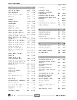
Page 320: ...T H I S P A G E H A S B E E N I N T E N T I O N A L L Y L E F T E M P T Y ANALYTICAL INDEX NOTE 10 Pegaso 650 I E 00 Release 00 2002 02 ...
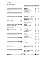
Reviews: