


ENGINE
3
- 14
Pegaso 650 I.E.
Follow
ã
◆
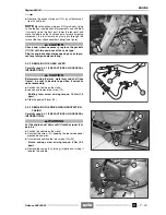
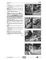
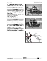
Unscrew and remove the nut (53) and withdraw the
rear lower screw (51) that fastens the engine to the
frame.
Small pedal screw driving torque: 50 Nm (5.0 kgm).
a
CAUTION
Once the screw (51) has been withdrawn, the engine
will tend to turn slightly forward with fulcrum on the
screw (52).
NOTE
To make it easier to withdraw the screw (51),
slightly raise the engine.
◆
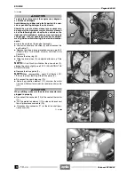
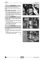
Unscrew and remove the nut (54) and withdraw the up-
per screw (52) that fastens the engine to the frame, tak-
ing the washer.
a
CAUTION
Clear the floor, on which the engine is to be set down,
of any tools and clean thoroughly.
a
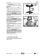
WARNING
The engine is now completely free and has nothing
fastening it. Handle with care: watch your fingers and
limbs.
Grasp the engine on both sides, where it can be held
firmly, and extract it gradually from the left side, try-
ing to find the optimal combination of movements.
◆
Lower the hoist arm until the engine is gently set down
on the floor.
◆
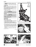
Secure the engine so that it does not fall over if poorly
balanced.
NOTE
If the engine is to be worked on, set it on the rel-
evant stand (55), see 3.3.1 (POSITIONING THE ENGINE
ON THE ENGINE SUPPORT STAND).
a
CAUTION
If no work is to be performed on the engine, leave it
rested on the floor and attached to the bands (A) and
hoist for extra safety.
◆
Complete the cleaning of the engine outside with the ut-
most care.
a
CAUTION
Use a detergent, brushes and rags to clean the en-
gines outer surfaces.
Avoid damaging rubber and plastic parts with corro-
sive or penetrating detergents and solvents.
Release 00/2002-02
- 00
Release 00/2002-02
- 00
Summary of Contents for Pegaso 650 I.E.
Page 11: ...1 1 Pegaso 650 I E GENERAL INFORMATION 1 Release 00 2002 02 00 ...
Page 24: ...GENERAL INFORMATION 1 14 Pegaso 650 I E 1 7 2 GENERIC TOOLS Release 00 2002 02 00 ...
Page 39: ...2 1 Pegaso 650 I E 1 SERVICE AND SETTING UP 2 Release 00 2002 02 00 ...
Page 45: ...SERVICE AND SETTING UP 2 7 Pegaso 650 I E LUBRICATION CHART Release 00 2002 02 00 ...
Page 95: ...3 1 Pegaso 650 I E 1 3 ENGINE 3 Release 00 2002 02 00 ...
Page 99: ...ENGINE 3 5 Pegaso 650 I E Release 00 2002 02 00 ...
Page 113: ...4 1 Pegaso 650 I E 1 2 3 FUEL SUPPLY SYSTEM 4 Release 00 2002 02 00 ...
Page 139: ...5 1 Pegaso 650 I E 1 2 3 4 COOLING SYSTEM 5 Release 00 2002 02 00 ...
Page 149: ...6 1 Pegaso 650 I E 1 2 3 4 5 ELECTRIC SYSTEM 6 Release 00 2002 02 00 ...
Page 152: ...6 4 ELECTRIC SYSTEM Pegaso 650 I E 42 0 43 9 54 00 Release 00 2002 02 ...
Page 190: ...ELECTRIC SYSTEM 6 42 Pegaso 650 I E 7 2 2 Release 00 2002 02 00 ...
Page 193: ...7 1 Pegaso 650 I E 1 2 3 4 5 6 CHASSIS 7 Release 00 2002 02 00 ...
Page 287: ...1 2 3 4 5 6 7 8 1 Pegaso 650 I E 1 2 3 4 5 6 7 REPAIR INFORMATION 8 Release 00 2002 02 00 ...
Page 297: ...REPAIR INFORMATION 8 11 Pegaso 650 I E 8 2 3 FUEL SYSTEM PIPES Release 00 2002 02 00 ...
Page 298: ...REPAIR INFORMATION 8 12 Pegaso 650 I E 8 2 4 ENGINE OIL PIPES Release 00 2002 02 00 ...
Page 304: ...REPAIR INFORMATION 8 18 Pegaso 650 I E Release 00 2002 02 00 ...
Page 305: ...Pegaso 650 I E REPAIR INFORMATION 8 19 Release 00 2002 02 00 ...
Page 306: ...REPAIR INFORMATION 8 20 Pegaso 650 I E Release 00 2002 02 00 ...
Page 307: ...REPAIR INFORMATION 8 21 Pegaso 650 I E Release 00 2002 02 00 ...
Page 311: ... 1 Pegaso 650 I E ANALYTICAL INDEX 00 Release 00 2002 02 ...
Page 317: ...ANALYTICAL INDEX 7 Pegaso 650 I E 9 2IF 0AGE 2IF 0AGE 00 Release 00 2002 02 ...


