


CHASSIS
7
- 80
Pegaso 650 I.E.
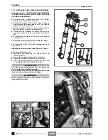
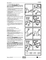
7.8.6 REASSEMBLING THE WHEEL-HOLDER TUBE -
SLIDER UNIT
Carefully read 0.5.1 (PRECAUTIONS AND GENERAL
INFORMATIONS), 1.2.3 (FORK OIL) and 2.24 (IN-
SPECTING THE FRONT AND REAR SUSPENSION).
NOTE
The operations marked with the symbol “
✱
” are
valid also for the fork oil change.
a
CAUTION
Upon reassembly, proceed with the greatest care and
make sure that the sliding surfaces are in perfect
conditions (there must no be signs of wear, lines,
etc.), otherwise change the component.
Be careful to prevent any foreign matter from getting
inside.
Do not reuse any oil that has already been drained.
Always replace the gaskets.
The reassembly must be carried out with the greatest
care.
◆
Before reinstalling the gaskets and the bushes, spread
a film of fork oil on them, see 1.6 (LUBR ICANT
CHART).
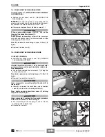
◆
If it has been removed, install the slide bush (2) on the
tube (1), using a special pad.
◆
Insert the bottom pad (4) on the base of the pumping el-
ement (3).
a
CAUTION
If the ring (A) on the pumping element is worn,
change it.
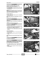
◆
Introduce the whole pumping element (3) into the tube
(1).
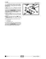
◆
Position the slider (5) in the vice, interposing jaws made
of a soft material (aluminium).
◆
If it has been removed, install the guide bush (6) on the
slider, using a special pad.
◆
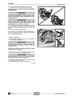
Insert the cap (7).
◆
Install the new sealing ring (8).
◆
Insert the tube assembly (1) into the slider (5).
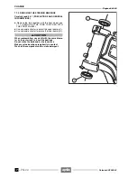
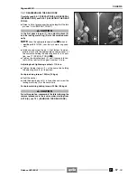
◆
Position the copper washer (10) on the centre screw
(9).
◆
Insert and tighten the centre screw (9).
Right slider centre screw driving torque: 50 Nm (5.0
kgm).
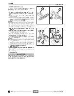
◆
Apply adhesive tape to the end of the slider without
making it overlap, in such a way as to protect the gas-
ket upon reassembly.
Follow
ã
Release 00/2002-02
- 00
Summary of Contents for Pegaso 650 I.E.
Page 11: ...1 1 Pegaso 650 I E GENERAL INFORMATION 1 Release 00 2002 02 00 ...
Page 24: ...GENERAL INFORMATION 1 14 Pegaso 650 I E 1 7 2 GENERIC TOOLS Release 00 2002 02 00 ...
Page 39: ...2 1 Pegaso 650 I E 1 SERVICE AND SETTING UP 2 Release 00 2002 02 00 ...
Page 45: ...SERVICE AND SETTING UP 2 7 Pegaso 650 I E LUBRICATION CHART Release 00 2002 02 00 ...
Page 95: ...3 1 Pegaso 650 I E 1 3 ENGINE 3 Release 00 2002 02 00 ...
Page 99: ...ENGINE 3 5 Pegaso 650 I E Release 00 2002 02 00 ...
Page 113: ...4 1 Pegaso 650 I E 1 2 3 FUEL SUPPLY SYSTEM 4 Release 00 2002 02 00 ...
Page 139: ...5 1 Pegaso 650 I E 1 2 3 4 COOLING SYSTEM 5 Release 00 2002 02 00 ...
Page 149: ...6 1 Pegaso 650 I E 1 2 3 4 5 ELECTRIC SYSTEM 6 Release 00 2002 02 00 ...
Page 152: ...6 4 ELECTRIC SYSTEM Pegaso 650 I E 42 0 43 9 54 00 Release 00 2002 02 ...
Page 190: ...ELECTRIC SYSTEM 6 42 Pegaso 650 I E 7 2 2 Release 00 2002 02 00 ...
Page 193: ...7 1 Pegaso 650 I E 1 2 3 4 5 6 CHASSIS 7 Release 00 2002 02 00 ...
Page 287: ...1 2 3 4 5 6 7 8 1 Pegaso 650 I E 1 2 3 4 5 6 7 REPAIR INFORMATION 8 Release 00 2002 02 00 ...
Page 297: ...REPAIR INFORMATION 8 11 Pegaso 650 I E 8 2 3 FUEL SYSTEM PIPES Release 00 2002 02 00 ...
Page 298: ...REPAIR INFORMATION 8 12 Pegaso 650 I E 8 2 4 ENGINE OIL PIPES Release 00 2002 02 00 ...
Page 304: ...REPAIR INFORMATION 8 18 Pegaso 650 I E Release 00 2002 02 00 ...
Page 305: ...Pegaso 650 I E REPAIR INFORMATION 8 19 Release 00 2002 02 00 ...
Page 306: ...REPAIR INFORMATION 8 20 Pegaso 650 I E Release 00 2002 02 00 ...
Page 307: ...REPAIR INFORMATION 8 21 Pegaso 650 I E Release 00 2002 02 00 ...
Page 311: ... 1 Pegaso 650 I E ANALYTICAL INDEX 00 Release 00 2002 02 ...
Page 317: ...ANALYTICAL INDEX 7 Pegaso 650 I E 9 2IF 0AGE 2IF 0AGE 00 Release 00 2002 02 ...


