7
- 67
CHASSIS
Pegaso 650 I.E.
a
CAUTION
Prepare a new clamp to replace the original.
◆
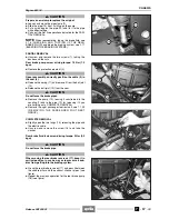
Loosen and move the pipe clamp (9).
◆
Slide the pipe (10) from its fitting on the pump.
◆
Put a nylon bag on the pipe (10) and fix it to the pipe
with adhesive tape.
◆
Carry out the first five operations indicated for the PAR-
TIAL REMOVAL.
NOTE
When reassembling, top up the brake fluid, see
2.16 (CHECKING AND TOPPING UP THE REAR
BRAKE FLUID) and bleed the braking system, see 2.17
(BLEEDING THE BRAKING SYSTEMS).
PARTIAL REMOVAL
◆
Unscrew and remove the two screws (1), taking the
bushes and the nuts.
Rear brake pump screw driving torque: 10 Nm (1.0
kgm).
◆
Remove the protection element (2).
a
CAUTION
Upon reassembly, correctly position the cable (3) in
the seat (4).
◆
Release the spring (11) and remove it from the ball joint
(12).
◆
Release the ball joint (12) from the seat.
a
CAUTION
Do not force the brake pipes.
◆
Remove the pump (13), leaving it constrained to the
coupling (7) and to the pipe (10) (or releasing it if you
are carrying out a COMPLETE REMOVAL).
◆
Remove the right passenger footrest unit, see 7.1.33
( R E M O V I N G T H E PA S S E N G E R F O O T R E S T
GROUP).
COMPLETE REMOVAL
◆
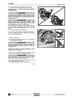
Slightly open the two tangs (15), releasing the pipe and
the electric cable.
◆
Unscrew and remove the screw (16) and take the
washer.
Rear brake fluid tank screw driving torque: 3 Nm (0.3
kgm).
a
CAUTION
Do not force the brake pipe.
a
CAUTION
When moving the rear brake reservoir (17), keep it in
vertical position, in such a way as to prevent air bub-
bles from getting into the braking system.
◆
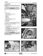
Grasp the rear brake reservoir (17) and pass it between
the saddle pillar and the exhaust silencer pipes (see
figure).
◆
Repeat the previous operation for the rear brake pump
(18) (see figure).
Release 00/2002-02
- 00
Summary of Contents for Pegaso 650 I.E.
Page 11: ...1 1 Pegaso 650 I E GENERAL INFORMATION 1 Release 00 2002 02 00 ...
Page 24: ...GENERAL INFORMATION 1 14 Pegaso 650 I E 1 7 2 GENERIC TOOLS Release 00 2002 02 00 ...
Page 39: ...2 1 Pegaso 650 I E 1 SERVICE AND SETTING UP 2 Release 00 2002 02 00 ...
Page 45: ...SERVICE AND SETTING UP 2 7 Pegaso 650 I E LUBRICATION CHART Release 00 2002 02 00 ...
Page 95: ...3 1 Pegaso 650 I E 1 3 ENGINE 3 Release 00 2002 02 00 ...
Page 99: ...ENGINE 3 5 Pegaso 650 I E Release 00 2002 02 00 ...
Page 113: ...4 1 Pegaso 650 I E 1 2 3 FUEL SUPPLY SYSTEM 4 Release 00 2002 02 00 ...
Page 139: ...5 1 Pegaso 650 I E 1 2 3 4 COOLING SYSTEM 5 Release 00 2002 02 00 ...
Page 149: ...6 1 Pegaso 650 I E 1 2 3 4 5 ELECTRIC SYSTEM 6 Release 00 2002 02 00 ...
Page 152: ...6 4 ELECTRIC SYSTEM Pegaso 650 I E 42 0 43 9 54 00 Release 00 2002 02 ...
Page 190: ...ELECTRIC SYSTEM 6 42 Pegaso 650 I E 7 2 2 Release 00 2002 02 00 ...
Page 193: ...7 1 Pegaso 650 I E 1 2 3 4 5 6 CHASSIS 7 Release 00 2002 02 00 ...
Page 287: ...1 2 3 4 5 6 7 8 1 Pegaso 650 I E 1 2 3 4 5 6 7 REPAIR INFORMATION 8 Release 00 2002 02 00 ...
Page 297: ...REPAIR INFORMATION 8 11 Pegaso 650 I E 8 2 3 FUEL SYSTEM PIPES Release 00 2002 02 00 ...
Page 298: ...REPAIR INFORMATION 8 12 Pegaso 650 I E 8 2 4 ENGINE OIL PIPES Release 00 2002 02 00 ...
Page 304: ...REPAIR INFORMATION 8 18 Pegaso 650 I E Release 00 2002 02 00 ...
Page 305: ...Pegaso 650 I E REPAIR INFORMATION 8 19 Release 00 2002 02 00 ...
Page 306: ...REPAIR INFORMATION 8 20 Pegaso 650 I E Release 00 2002 02 00 ...
Page 307: ...REPAIR INFORMATION 8 21 Pegaso 650 I E Release 00 2002 02 00 ...
Page 311: ... 1 Pegaso 650 I E ANALYTICAL INDEX 00 Release 00 2002 02 ...
Page 317: ...ANALYTICAL INDEX 7 Pegaso 650 I E 9 2IF 0AGE 2IF 0AGE 00 Release 00 2002 02 ...


