SERVICE AND SETTING UP
2
- 52
Pegaso 650 I.E.
#(%#+).' 4(% 34!.$
Carefully read 0.5.1 (PRECAUTIONS AND GENERAL
INFORMATIONS) and 6.8 (SWITCHES).
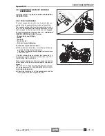
The vehicle is provided with:
– side stand (1);
– centre stand (2)
m
(supplied as standard equipment
in the countries where required).
The stand has two positions:
– normal or lifted;
– extended.
It is the rider who must provide for extending and lifting
the stand.
The stand must rotate without hindrances.
The springs (3) provide for keeping the stand in the de-
sired position (extended or lifted).
SIDE STAND
◆
Position the vehicle on the centre stand
m
.
◆
The springs (3) must not be damaged, worn, rusty or
weakened.
◆
Make sure that the stand presents no slack in either po-
sition (extended and lifted).
◆
Lower the stand, making sure that the springs provide
for extending it completely.
◆
Move the stand to let it up and release it halfway to
make sure that the springs provide for lifting it com-
pletely.
◆
The side stand must rotate freely, if necessary grease
the joint, see 1.6 (LUBRICANT CHART).
a
WARNING
If the side stand has wrong rotation and inclination
angles, when the vehicle is parked the stability of the
vehicle may be affected, with the consequent risk of
overturning of the vehicle itself.
◆
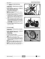
Check the angle of rotation (C) of the stand between
the two positions (A) and (B).
Stand rotation angle: 106° ± 3°.
◆
With the stand in position (B), check its inclination angle
(D) with respect to the vertical axis.
◆
Stand inclination angle: 47° ± 3°.
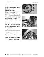
The side stand (1) is provided with a safety switch (4) that
has the function to prevent or interrupt the operation of
the engine with the gears on and the side stand (1) down.
Release 00/2002-02
- 00
Summary of Contents for Pegaso 650 I.E.
Page 11: ...1 1 Pegaso 650 I E GENERAL INFORMATION 1 Release 00 2002 02 00 ...
Page 24: ...GENERAL INFORMATION 1 14 Pegaso 650 I E 1 7 2 GENERIC TOOLS Release 00 2002 02 00 ...
Page 39: ...2 1 Pegaso 650 I E 1 SERVICE AND SETTING UP 2 Release 00 2002 02 00 ...
Page 45: ...SERVICE AND SETTING UP 2 7 Pegaso 650 I E LUBRICATION CHART Release 00 2002 02 00 ...
Page 95: ...3 1 Pegaso 650 I E 1 3 ENGINE 3 Release 00 2002 02 00 ...
Page 99: ...ENGINE 3 5 Pegaso 650 I E Release 00 2002 02 00 ...
Page 113: ...4 1 Pegaso 650 I E 1 2 3 FUEL SUPPLY SYSTEM 4 Release 00 2002 02 00 ...
Page 139: ...5 1 Pegaso 650 I E 1 2 3 4 COOLING SYSTEM 5 Release 00 2002 02 00 ...
Page 149: ...6 1 Pegaso 650 I E 1 2 3 4 5 ELECTRIC SYSTEM 6 Release 00 2002 02 00 ...
Page 152: ...6 4 ELECTRIC SYSTEM Pegaso 650 I E 42 0 43 9 54 00 Release 00 2002 02 ...
Page 190: ...ELECTRIC SYSTEM 6 42 Pegaso 650 I E 7 2 2 Release 00 2002 02 00 ...
Page 193: ...7 1 Pegaso 650 I E 1 2 3 4 5 6 CHASSIS 7 Release 00 2002 02 00 ...
Page 287: ...1 2 3 4 5 6 7 8 1 Pegaso 650 I E 1 2 3 4 5 6 7 REPAIR INFORMATION 8 Release 00 2002 02 00 ...
Page 297: ...REPAIR INFORMATION 8 11 Pegaso 650 I E 8 2 3 FUEL SYSTEM PIPES Release 00 2002 02 00 ...
Page 298: ...REPAIR INFORMATION 8 12 Pegaso 650 I E 8 2 4 ENGINE OIL PIPES Release 00 2002 02 00 ...
Page 304: ...REPAIR INFORMATION 8 18 Pegaso 650 I E Release 00 2002 02 00 ...
Page 305: ...Pegaso 650 I E REPAIR INFORMATION 8 19 Release 00 2002 02 00 ...
Page 306: ...REPAIR INFORMATION 8 20 Pegaso 650 I E Release 00 2002 02 00 ...
Page 307: ...REPAIR INFORMATION 8 21 Pegaso 650 I E Release 00 2002 02 00 ...
Page 311: ... 1 Pegaso 650 I E ANALYTICAL INDEX 00 Release 00 2002 02 ...
Page 317: ...ANALYTICAL INDEX 7 Pegaso 650 I E 9 2IF 0AGE 2IF 0AGE 00 Release 00 2002 02 ...


