7
- 77
CHASSIS
Pegaso 650 I.E.
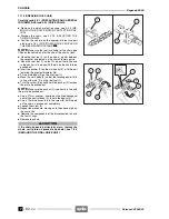
7.8.4 DISASSEMBLING THE SLIDER-TUBE
ASSEMBLIES
Carefully read 0.5.1 (PRECAUTIONS AND GENERAL
INFORMATIONS), 1.2.3 (FORK OIL) and 2.24 (IN-
SPECTING THE FRONT AND REAR SUSPENSION).
NOTE
The right and left slider-tube assemblies have
the same inner components.
The operations described below are referred to a single
wheel-holder tube - slider unit, but are valid for both.
The operations marked with the symbol “
✱
” are valid also
for the fork oil change.
◆ ✱
Remove the slider-tube assembly, see 7.8.3 (RE-
MOVING THE SLIDER-TUBE ASSEMBLIES).
◆ ✱
Carefully clean the entire slider-tube assembly.
◆
Prepare a container with capacity exceeding 570 cm
#
.
a
CAUTION
The disassembly must be performed very carefully.
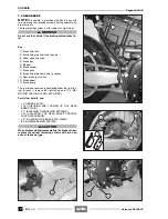
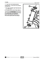
◆
Position the tube (1) on a vice, interposing clamps
made of soft material (aluminium).
a
CAUTION
The slider-tube assembly contains oil; neither over-
turn, nor incline it excessively during disassembly.
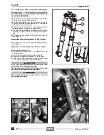
◆
Unscrew and remove the tube upper plug (2).
Fork tube plug driving torque: 20 Nm (2.0 kgm).
a
CAUTION
Upon reassembly, replace the O-ring (3).
◆ ✱
Remove the preload tube (4).
◆
Remove the spring (5).
◆ ✱
Remove the slider-tube assembly from the vice.
a
CAUTION
It is advisable to use latex gloves.
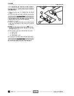
◆ ✱
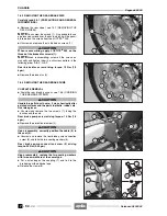
Overturn the slider-tube assembly (2), draining the
oil into the container (6).
NOTE
To let all the oil flow out, pump the tube (1) into
the slider slowly more than once.
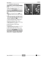
◆
Position the slider-tube assembly in the vice as indicat-
ed in the figure (A).
◆
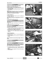
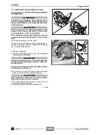
Remove the antidust gasket (7) from the slider by alter-
nately levering on more points with a cut-tipped screw-
driver.
Follow
ã
Release 00/2002-02
- 00
Summary of Contents for Pegaso 650 I.E.
Page 11: ...1 1 Pegaso 650 I E GENERAL INFORMATION 1 Release 00 2002 02 00 ...
Page 24: ...GENERAL INFORMATION 1 14 Pegaso 650 I E 1 7 2 GENERIC TOOLS Release 00 2002 02 00 ...
Page 39: ...2 1 Pegaso 650 I E 1 SERVICE AND SETTING UP 2 Release 00 2002 02 00 ...
Page 45: ...SERVICE AND SETTING UP 2 7 Pegaso 650 I E LUBRICATION CHART Release 00 2002 02 00 ...
Page 95: ...3 1 Pegaso 650 I E 1 3 ENGINE 3 Release 00 2002 02 00 ...
Page 99: ...ENGINE 3 5 Pegaso 650 I E Release 00 2002 02 00 ...
Page 113: ...4 1 Pegaso 650 I E 1 2 3 FUEL SUPPLY SYSTEM 4 Release 00 2002 02 00 ...
Page 139: ...5 1 Pegaso 650 I E 1 2 3 4 COOLING SYSTEM 5 Release 00 2002 02 00 ...
Page 149: ...6 1 Pegaso 650 I E 1 2 3 4 5 ELECTRIC SYSTEM 6 Release 00 2002 02 00 ...
Page 152: ...6 4 ELECTRIC SYSTEM Pegaso 650 I E 42 0 43 9 54 00 Release 00 2002 02 ...
Page 190: ...ELECTRIC SYSTEM 6 42 Pegaso 650 I E 7 2 2 Release 00 2002 02 00 ...
Page 193: ...7 1 Pegaso 650 I E 1 2 3 4 5 6 CHASSIS 7 Release 00 2002 02 00 ...
Page 287: ...1 2 3 4 5 6 7 8 1 Pegaso 650 I E 1 2 3 4 5 6 7 REPAIR INFORMATION 8 Release 00 2002 02 00 ...
Page 297: ...REPAIR INFORMATION 8 11 Pegaso 650 I E 8 2 3 FUEL SYSTEM PIPES Release 00 2002 02 00 ...
Page 298: ...REPAIR INFORMATION 8 12 Pegaso 650 I E 8 2 4 ENGINE OIL PIPES Release 00 2002 02 00 ...
Page 304: ...REPAIR INFORMATION 8 18 Pegaso 650 I E Release 00 2002 02 00 ...
Page 305: ...Pegaso 650 I E REPAIR INFORMATION 8 19 Release 00 2002 02 00 ...
Page 306: ...REPAIR INFORMATION 8 20 Pegaso 650 I E Release 00 2002 02 00 ...
Page 307: ...REPAIR INFORMATION 8 21 Pegaso 650 I E Release 00 2002 02 00 ...
Page 311: ... 1 Pegaso 650 I E ANALYTICAL INDEX 00 Release 00 2002 02 ...
Page 317: ...ANALYTICAL INDEX 7 Pegaso 650 I E 9 2IF 0AGE 2IF 0AGE 00 Release 00 2002 02 ...


