


7
- 21
CHASSIS
Pegaso 650 I.E.
7.1.24 REMOVING THE FRONT FAIRING
Carefully read 0.5.1 (PRECAUTIONS AND GENERAL
INFORMATIONS).
a
WARNING
Let the engine cool down until it reaches room tem-
perature.
◆
Remove the dashboard fairing, see 7.1.27 (REMOV-
ING THE DASHBOARD FAIRING).
◆
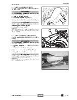
Disconnect the electric connector (1) of the headlight.
~
Disconnect the electric connectors of the front direc-
tion indicators (2) (3).
~
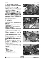
Unscrew and remove the screw (4), retrieving the
rubber element if necessary.
Front fairing rear screw driving torque: 25 Nm (2.5
kgm).
~
Unscrew and remove the screw (5).
Front fairing side screw driving torque: 25 Nm (2.5
kgm).
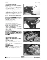
◆
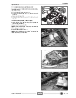
Unscrew and remove the screw (6).
Front fairing upper screw driving torque: 25 Nm (2.5
kgm).
◆
Unscrew and remove the screws (7).
Front fairing front screw driving torque: 25 Nm (2.5
kgm).
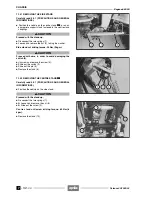
◆
Unscrew and remove the screw (8), releasing the cable
guide collar (9) and if necessary take the rubber ele-
ment.
NOTE
Upon reassembly, position the cable guide col-
lar (9) correctly.
a
CAUTION
Proceed with care.
Do not damage the tangs and/or their seats.
Handle the painted components with care and avoid
scraping or damaging them.
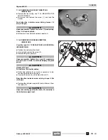
◆
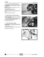
Slightly open the lower part of the fairing and at the
same time move it slightly forward.
◆
Remove the fairing (10), complete with headlight, front
direction indicators, screen (11) and transparent front
part of the fairing (12).
NOTE
Upon reassembly, position the front fairing cor-
rectly, making all the coupling and fastening points coin-
cide.
◆
Where necessary, remove the headlight, see 7.1.25
(REMOVING THE HEADLIGHT) and the direction indi-
cators, see 7.1.43 (REMOVING THE FRONT DIREC-
TION INDICATORS).
Release 00/2002-02
- 00
Summary of Contents for Pegaso 650 I.E.
Page 11: ...1 1 Pegaso 650 I E GENERAL INFORMATION 1 Release 00 2002 02 00 ...
Page 24: ...GENERAL INFORMATION 1 14 Pegaso 650 I E 1 7 2 GENERIC TOOLS Release 00 2002 02 00 ...
Page 39: ...2 1 Pegaso 650 I E 1 SERVICE AND SETTING UP 2 Release 00 2002 02 00 ...
Page 45: ...SERVICE AND SETTING UP 2 7 Pegaso 650 I E LUBRICATION CHART Release 00 2002 02 00 ...
Page 95: ...3 1 Pegaso 650 I E 1 3 ENGINE 3 Release 00 2002 02 00 ...
Page 99: ...ENGINE 3 5 Pegaso 650 I E Release 00 2002 02 00 ...
Page 113: ...4 1 Pegaso 650 I E 1 2 3 FUEL SUPPLY SYSTEM 4 Release 00 2002 02 00 ...
Page 139: ...5 1 Pegaso 650 I E 1 2 3 4 COOLING SYSTEM 5 Release 00 2002 02 00 ...
Page 149: ...6 1 Pegaso 650 I E 1 2 3 4 5 ELECTRIC SYSTEM 6 Release 00 2002 02 00 ...
Page 152: ...6 4 ELECTRIC SYSTEM Pegaso 650 I E 42 0 43 9 54 00 Release 00 2002 02 ...
Page 190: ...ELECTRIC SYSTEM 6 42 Pegaso 650 I E 7 2 2 Release 00 2002 02 00 ...
Page 193: ...7 1 Pegaso 650 I E 1 2 3 4 5 6 CHASSIS 7 Release 00 2002 02 00 ...
Page 287: ...1 2 3 4 5 6 7 8 1 Pegaso 650 I E 1 2 3 4 5 6 7 REPAIR INFORMATION 8 Release 00 2002 02 00 ...
Page 297: ...REPAIR INFORMATION 8 11 Pegaso 650 I E 8 2 3 FUEL SYSTEM PIPES Release 00 2002 02 00 ...
Page 298: ...REPAIR INFORMATION 8 12 Pegaso 650 I E 8 2 4 ENGINE OIL PIPES Release 00 2002 02 00 ...
Page 304: ...REPAIR INFORMATION 8 18 Pegaso 650 I E Release 00 2002 02 00 ...
Page 305: ...Pegaso 650 I E REPAIR INFORMATION 8 19 Release 00 2002 02 00 ...
Page 306: ...REPAIR INFORMATION 8 20 Pegaso 650 I E Release 00 2002 02 00 ...
Page 307: ...REPAIR INFORMATION 8 21 Pegaso 650 I E Release 00 2002 02 00 ...
Page 311: ... 1 Pegaso 650 I E ANALYTICAL INDEX 00 Release 00 2002 02 ...
Page 317: ...ANALYTICAL INDEX 7 Pegaso 650 I E 9 2IF 0AGE 2IF 0AGE 00 Release 00 2002 02 ...


