


SERVICE AND SETTING UP
2
- 23
Pegaso 650 I.E.
#(!.').' 4(% #//,!.4
Carefully read 0.5.1 (PRECAUTIONS AND GENERAL
INFORMATIONS) and 1.2.5 (COOLANT).
For the maintenance intervals, see 2.1.1 (REGULAR
SERVICE INTERVALS CHART) under:
– Coolant.
◆
Remove the oil sump guard, see 7.1.3 (REMOVING
THE OIL SUMP GUARD).
◆
R emove the fuel tank, see 7.1.1 (REMOVAL OF THE
FUEL TANK).
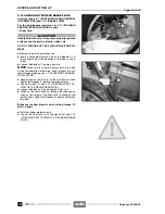
◆
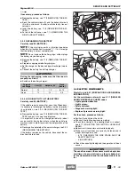
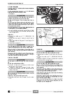
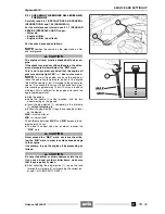
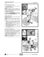
Place a container (4) under the drain screw (3) to catch
the coolant (capacity over 2.5
L
).
◆
Unscrew and remove the drain screw (3) retrieving the
copper washer.
a
CAUTION
Do not remove the filler cap (1) when the engine is
hot as the coolant is under pressure and is very hot.
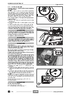
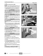
◆
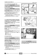
To facilitate the fluid outflow, remove the circuit filling
cap (5) and successively the expansion tank filling cap
(1) positioned on the expansion tank.
DO NOT DISPOSE OF THE FLUID IN THE ENVIRON-
MENT.
◆
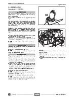
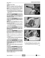
Reassemble the drain screw (3) with a new copper
washer.
Driving torque of the coolant drain screw: 12 Nm (1.2
kgm).
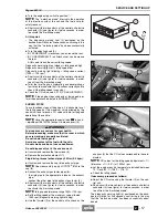
◆
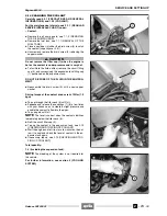
Top up through the filler neck (6) until full.
◆
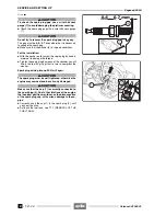
Squeeze and release the couplings (7) (8) a few times
with your hands so as to create a slight pressure and
enable the coolant to flow into the pipes.
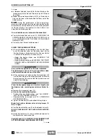
◆
Top up again until full.
NOTE
The level is correct when the coolant stabilizes
immediately below the filler neck (6).
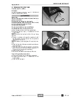
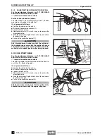
◆
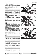
Refit the circuit filler cap (5).
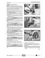
◆
Top up the coolant in the expansion tank, see 2.13
(CHECKING AND TOPPING UP COOLANT).
◆
Start the engine and let it run for a few minutes, then al-
low it to cool and check the level of coolant in the ex-
pansion tank again.
◆
If necessary, top up, see 2.13 (CHECKING AND TOP-
PING UP COOLANT).
Total quantity:
1.4
L
(including the expansion tank).
NOTE
The bleeding of the system is not required for
this vehicle.
For further information, see section 5 (COOLING
SYSTEM).
Release 00/2002-02
- 00
Summary of Contents for Pegaso 650 I.E.
Page 11: ...1 1 Pegaso 650 I E GENERAL INFORMATION 1 Release 00 2002 02 00 ...
Page 24: ...GENERAL INFORMATION 1 14 Pegaso 650 I E 1 7 2 GENERIC TOOLS Release 00 2002 02 00 ...
Page 39: ...2 1 Pegaso 650 I E 1 SERVICE AND SETTING UP 2 Release 00 2002 02 00 ...
Page 45: ...SERVICE AND SETTING UP 2 7 Pegaso 650 I E LUBRICATION CHART Release 00 2002 02 00 ...
Page 95: ...3 1 Pegaso 650 I E 1 3 ENGINE 3 Release 00 2002 02 00 ...
Page 99: ...ENGINE 3 5 Pegaso 650 I E Release 00 2002 02 00 ...
Page 113: ...4 1 Pegaso 650 I E 1 2 3 FUEL SUPPLY SYSTEM 4 Release 00 2002 02 00 ...
Page 139: ...5 1 Pegaso 650 I E 1 2 3 4 COOLING SYSTEM 5 Release 00 2002 02 00 ...
Page 149: ...6 1 Pegaso 650 I E 1 2 3 4 5 ELECTRIC SYSTEM 6 Release 00 2002 02 00 ...
Page 152: ...6 4 ELECTRIC SYSTEM Pegaso 650 I E 42 0 43 9 54 00 Release 00 2002 02 ...
Page 190: ...ELECTRIC SYSTEM 6 42 Pegaso 650 I E 7 2 2 Release 00 2002 02 00 ...
Page 193: ...7 1 Pegaso 650 I E 1 2 3 4 5 6 CHASSIS 7 Release 00 2002 02 00 ...
Page 287: ...1 2 3 4 5 6 7 8 1 Pegaso 650 I E 1 2 3 4 5 6 7 REPAIR INFORMATION 8 Release 00 2002 02 00 ...
Page 297: ...REPAIR INFORMATION 8 11 Pegaso 650 I E 8 2 3 FUEL SYSTEM PIPES Release 00 2002 02 00 ...
Page 298: ...REPAIR INFORMATION 8 12 Pegaso 650 I E 8 2 4 ENGINE OIL PIPES Release 00 2002 02 00 ...
Page 304: ...REPAIR INFORMATION 8 18 Pegaso 650 I E Release 00 2002 02 00 ...
Page 305: ...Pegaso 650 I E REPAIR INFORMATION 8 19 Release 00 2002 02 00 ...
Page 306: ...REPAIR INFORMATION 8 20 Pegaso 650 I E Release 00 2002 02 00 ...
Page 307: ...REPAIR INFORMATION 8 21 Pegaso 650 I E Release 00 2002 02 00 ...
Page 311: ... 1 Pegaso 650 I E ANALYTICAL INDEX 00 Release 00 2002 02 ...
Page 317: ...ANALYTICAL INDEX 7 Pegaso 650 I E 9 2IF 0AGE 2IF 0AGE 00 Release 00 2002 02 ...


