CHASSIS
7
- 82
Pegaso 650 I.E.
7.8.7 INSTALLING THE SLIDER-TUBE ASSEMBLIES
Carefully read 0.5.1 (PRECAUTIONS AND GENERAL
INFORMATIONS) and 2.24 (INSPECTING THE FRONT
AND REAR SUSPENSION).
~
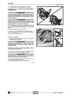
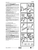
Insert the tube (1) complete with slider (2) in the low-
er plate (3) and in the upper plate (4).
~
Insert the wheel pin (5) on both tubes in order to
align the hole of the wheel-holder tube (2) with the hole
of the other wheel-holder tube.
~
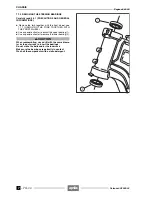
Make sure that the tube (1) is correctly inserted on
the lower plate (3) and on the upper plate (4).
◆
The tube must be inserted in the upper plate until its up-
per edge is aligned with the upper edge of the plate it-
self.
~
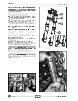
Tighten the two screws (6) that fix the lower plate (3)
to the tube (1).
Lower plate screw driving torque: 25 Nm (2.5 kgm).
~
Tighten the screw (7) that fixes the upper plate (4) to
the tube (1).
Upper plate screw driving torque: 50 Nm (5.0 kgm).
◆
Withdraw the wheel pin (5).
◆
Reassemble the wheel, see 7.2.1 (REMOVING THE
FRONT WHEEL).
◆
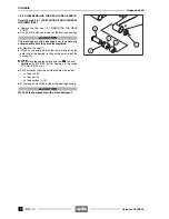
Connect the speedometer/odometer control (8).
◆
Connect the two electric terminals (9) of the horn.
◆
If the front fairing has been removed, reinstall it, see
7.1.24 (REMOVING THE FRONT FAIRING).
a
CAUTION
After the reassembly, operate the front brake and
thrust the fork repeatedly downwards.
The operation must be smooth and progressive and
there must be no trace of oil on the tubes.
a
WARNING
Before using the vehicle, check to make sure the rid-
ing position is correct.
Release 00/2002-02
- 00
Summary of Contents for Pegaso 650 I.E.
Page 11: ...1 1 Pegaso 650 I E GENERAL INFORMATION 1 Release 00 2002 02 00 ...
Page 24: ...GENERAL INFORMATION 1 14 Pegaso 650 I E 1 7 2 GENERIC TOOLS Release 00 2002 02 00 ...
Page 39: ...2 1 Pegaso 650 I E 1 SERVICE AND SETTING UP 2 Release 00 2002 02 00 ...
Page 45: ...SERVICE AND SETTING UP 2 7 Pegaso 650 I E LUBRICATION CHART Release 00 2002 02 00 ...
Page 95: ...3 1 Pegaso 650 I E 1 3 ENGINE 3 Release 00 2002 02 00 ...
Page 99: ...ENGINE 3 5 Pegaso 650 I E Release 00 2002 02 00 ...
Page 113: ...4 1 Pegaso 650 I E 1 2 3 FUEL SUPPLY SYSTEM 4 Release 00 2002 02 00 ...
Page 139: ...5 1 Pegaso 650 I E 1 2 3 4 COOLING SYSTEM 5 Release 00 2002 02 00 ...
Page 149: ...6 1 Pegaso 650 I E 1 2 3 4 5 ELECTRIC SYSTEM 6 Release 00 2002 02 00 ...
Page 152: ...6 4 ELECTRIC SYSTEM Pegaso 650 I E 42 0 43 9 54 00 Release 00 2002 02 ...
Page 190: ...ELECTRIC SYSTEM 6 42 Pegaso 650 I E 7 2 2 Release 00 2002 02 00 ...
Page 193: ...7 1 Pegaso 650 I E 1 2 3 4 5 6 CHASSIS 7 Release 00 2002 02 00 ...
Page 287: ...1 2 3 4 5 6 7 8 1 Pegaso 650 I E 1 2 3 4 5 6 7 REPAIR INFORMATION 8 Release 00 2002 02 00 ...
Page 297: ...REPAIR INFORMATION 8 11 Pegaso 650 I E 8 2 3 FUEL SYSTEM PIPES Release 00 2002 02 00 ...
Page 298: ...REPAIR INFORMATION 8 12 Pegaso 650 I E 8 2 4 ENGINE OIL PIPES Release 00 2002 02 00 ...
Page 304: ...REPAIR INFORMATION 8 18 Pegaso 650 I E Release 00 2002 02 00 ...
Page 305: ...Pegaso 650 I E REPAIR INFORMATION 8 19 Release 00 2002 02 00 ...
Page 306: ...REPAIR INFORMATION 8 20 Pegaso 650 I E Release 00 2002 02 00 ...
Page 307: ...REPAIR INFORMATION 8 21 Pegaso 650 I E Release 00 2002 02 00 ...
Page 311: ... 1 Pegaso 650 I E ANALYTICAL INDEX 00 Release 00 2002 02 ...
Page 317: ...ANALYTICAL INDEX 7 Pegaso 650 I E 9 2IF 0AGE 2IF 0AGE 00 Release 00 2002 02 ...

