CHASSIS
7
- 10
Pegaso 650 I.E.
7.1.9 REMOVING THE AIR CLEANER CASE
Carefully read 0.5.1 (PRECAUTIONS AND GENERAL
INFORMATIONS).
◆
Position the vehicle on the centre stand
m
.
◆
Remove the battery, see 7.1.8 (REMOVING THE BAT-
TERY).
◆
Remove the exhaust silencers, see 7.1.34 (REMOV-
ING THE EXHAUST SILENCERS).
NOTE
Have the appropriate special tool
m
to hand:
–
aprilia
part# 0277295 (hose clamp installation pliers).
a
CAUTION
Upon installation, replace the hose clamp that has
been removed with a new one having the same di-
mensions, see 0.4.2 (SPARE PARTS CATALOGUES).
Do not attempt to reinstall the removed hose clamp,
since it is unusable.
Do not replace the removed hose clamp with a screw
clamp or with other types of clamp.
◆
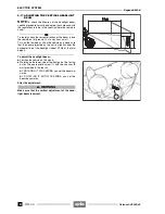
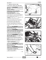
Release the hose clamp (1).
◆
Disconnect the pipe (2).
◆
Disconnect the pipe (3).
NOTE
To make it easier to withdraw the pipes (4) (5),
first withdraw the oil breather pipe (4) and then the petrol
breather pipe (5).
◆
Withdraw the two pipes (4) (5) from the clamp (6) and
from the cable guide (7).
NOTE
Upon reassembly, position the pipes correctly.
◆
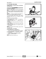
Remove the battery case (8).
◆
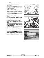
Unscrew and remove the screw (9), taking the nut and
the washers.
Filter case lower screw driving torque: 7 Nm (0.7
kgm).
◆
Unscrew and remove the two screws (10), taking the
relevant nuts.
Filter case rear screw driving torque: 10 Nm (1.0
kgm).
◆
Unscrew and remove the two screws (11), taking the
rubber elements and the bushes.
Filter case upper screw driving torque: 6 Nm (0.6
kgm).
◆
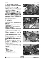
Disconnect the air temperature sensor connector (12).
◆
Partially remove the saddle support, see 7.1.36 (RE-
MOVING THE SADDLE SUPPORT).
◆
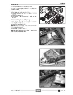
Move the filter case (13) forward, lower the rear part
and withdraw it from behind.
◆
Rotate and remove the air conveyor (15) and clean the
filtering element, see 2.8 (AIR CLEANER).
◆
Unscrew and remove the seven screws (16), taking the
relevant nuts.
◆
Remove the filter case cover (17).
◆
Check and if necessary change the following compo-
nents:
– plug gasket (18).
– gasket filter casing (19);
– inlet coupling (20);
– Acoustic insulation edging (21).
◆
Carefully clean the inside of the filter case.
Release 00/2002-02
- 00
Summary of Contents for Pegaso 650 I.E.
Page 11: ...1 1 Pegaso 650 I E GENERAL INFORMATION 1 Release 00 2002 02 00 ...
Page 24: ...GENERAL INFORMATION 1 14 Pegaso 650 I E 1 7 2 GENERIC TOOLS Release 00 2002 02 00 ...
Page 39: ...2 1 Pegaso 650 I E 1 SERVICE AND SETTING UP 2 Release 00 2002 02 00 ...
Page 45: ...SERVICE AND SETTING UP 2 7 Pegaso 650 I E LUBRICATION CHART Release 00 2002 02 00 ...
Page 95: ...3 1 Pegaso 650 I E 1 3 ENGINE 3 Release 00 2002 02 00 ...
Page 99: ...ENGINE 3 5 Pegaso 650 I E Release 00 2002 02 00 ...
Page 113: ...4 1 Pegaso 650 I E 1 2 3 FUEL SUPPLY SYSTEM 4 Release 00 2002 02 00 ...
Page 139: ...5 1 Pegaso 650 I E 1 2 3 4 COOLING SYSTEM 5 Release 00 2002 02 00 ...
Page 149: ...6 1 Pegaso 650 I E 1 2 3 4 5 ELECTRIC SYSTEM 6 Release 00 2002 02 00 ...
Page 152: ...6 4 ELECTRIC SYSTEM Pegaso 650 I E 42 0 43 9 54 00 Release 00 2002 02 ...
Page 190: ...ELECTRIC SYSTEM 6 42 Pegaso 650 I E 7 2 2 Release 00 2002 02 00 ...
Page 193: ...7 1 Pegaso 650 I E 1 2 3 4 5 6 CHASSIS 7 Release 00 2002 02 00 ...
Page 287: ...1 2 3 4 5 6 7 8 1 Pegaso 650 I E 1 2 3 4 5 6 7 REPAIR INFORMATION 8 Release 00 2002 02 00 ...
Page 297: ...REPAIR INFORMATION 8 11 Pegaso 650 I E 8 2 3 FUEL SYSTEM PIPES Release 00 2002 02 00 ...
Page 298: ...REPAIR INFORMATION 8 12 Pegaso 650 I E 8 2 4 ENGINE OIL PIPES Release 00 2002 02 00 ...
Page 304: ...REPAIR INFORMATION 8 18 Pegaso 650 I E Release 00 2002 02 00 ...
Page 305: ...Pegaso 650 I E REPAIR INFORMATION 8 19 Release 00 2002 02 00 ...
Page 306: ...REPAIR INFORMATION 8 20 Pegaso 650 I E Release 00 2002 02 00 ...
Page 307: ...REPAIR INFORMATION 8 21 Pegaso 650 I E Release 00 2002 02 00 ...
Page 311: ... 1 Pegaso 650 I E ANALYTICAL INDEX 00 Release 00 2002 02 ...
Page 317: ...ANALYTICAL INDEX 7 Pegaso 650 I E 9 2IF 0AGE 2IF 0AGE 00 Release 00 2002 02 ...

