


7
- 45
CHASSIS
Pegaso 650 I.E.
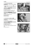
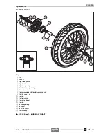
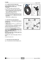
7.3.2 REMOVING THE FINAL DRIVE UNIT
Carefully read 0.5.1 (PRECAUTIONS AND GENERAL
INFORMATIONS).
◆
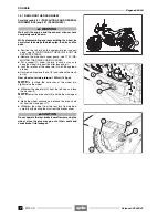
Remove the rear wheel, see 7.3.1 (REMOVING THE
REAR WHEEL).
NOTE
The support plate (8) complete with brake cali-
per (9) remains mounted on the left side of the rear fork.
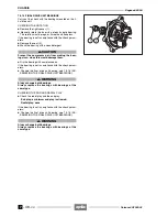
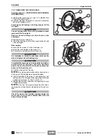
Proceed with care. If the final drive unit (10) is installed on
the flexible coupling holder (11), do not overturn or rotate
the rear wheel in horizontal position on the rear sprocket
side, since the final drive unit would come off and fall
down, with the risk of damaging the rear sprocket (7).
NOTE
The removal of the final drive unit isn’t neces-
sary if the wheel is in the normal running position (verti-
cal) or in horizontal position with the rear sprocket facing
upwards and in both cases secured against overturning.
NOTE
Do not unscrew the six nuts (12). The whole final
drive unit must be withdrawn from the flexible coupling hold-
er.
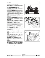
◆
Withdraw the final transmission unit (10), keeping it
parallel to the wheel axis.
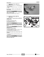
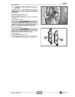
◆
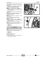
Remove the four flexible couplings (13) from the flexi-
ble coupling holder (11).
NOTE
Check the conditions of the four flexible couplings
(13); if they are damaged or excessively worn, change
them, see 2.1.1 (REGULAR SERVICE INTERVALS
CHART).
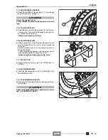
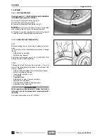
REASSEMBLY
NOTE
Insert the final transmission unit, parallel to the
wheel axis, introducing the drive pins in the relevant seats,
between a flexible coupling and the other.
◆
Position the four flexible couplings (13) in the relevant
seats in the flexible coupling holder (11).
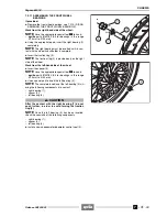
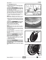
◆
Insert the final drive unit in the flexible coupling holder
(11).
Release 00/2002-02
- 00
Summary of Contents for Pegaso 650 I.E.
Page 11: ...1 1 Pegaso 650 I E GENERAL INFORMATION 1 Release 00 2002 02 00 ...
Page 24: ...GENERAL INFORMATION 1 14 Pegaso 650 I E 1 7 2 GENERIC TOOLS Release 00 2002 02 00 ...
Page 39: ...2 1 Pegaso 650 I E 1 SERVICE AND SETTING UP 2 Release 00 2002 02 00 ...
Page 45: ...SERVICE AND SETTING UP 2 7 Pegaso 650 I E LUBRICATION CHART Release 00 2002 02 00 ...
Page 95: ...3 1 Pegaso 650 I E 1 3 ENGINE 3 Release 00 2002 02 00 ...
Page 99: ...ENGINE 3 5 Pegaso 650 I E Release 00 2002 02 00 ...
Page 113: ...4 1 Pegaso 650 I E 1 2 3 FUEL SUPPLY SYSTEM 4 Release 00 2002 02 00 ...
Page 139: ...5 1 Pegaso 650 I E 1 2 3 4 COOLING SYSTEM 5 Release 00 2002 02 00 ...
Page 149: ...6 1 Pegaso 650 I E 1 2 3 4 5 ELECTRIC SYSTEM 6 Release 00 2002 02 00 ...
Page 152: ...6 4 ELECTRIC SYSTEM Pegaso 650 I E 42 0 43 9 54 00 Release 00 2002 02 ...
Page 190: ...ELECTRIC SYSTEM 6 42 Pegaso 650 I E 7 2 2 Release 00 2002 02 00 ...
Page 193: ...7 1 Pegaso 650 I E 1 2 3 4 5 6 CHASSIS 7 Release 00 2002 02 00 ...
Page 287: ...1 2 3 4 5 6 7 8 1 Pegaso 650 I E 1 2 3 4 5 6 7 REPAIR INFORMATION 8 Release 00 2002 02 00 ...
Page 297: ...REPAIR INFORMATION 8 11 Pegaso 650 I E 8 2 3 FUEL SYSTEM PIPES Release 00 2002 02 00 ...
Page 298: ...REPAIR INFORMATION 8 12 Pegaso 650 I E 8 2 4 ENGINE OIL PIPES Release 00 2002 02 00 ...
Page 304: ...REPAIR INFORMATION 8 18 Pegaso 650 I E Release 00 2002 02 00 ...
Page 305: ...Pegaso 650 I E REPAIR INFORMATION 8 19 Release 00 2002 02 00 ...
Page 306: ...REPAIR INFORMATION 8 20 Pegaso 650 I E Release 00 2002 02 00 ...
Page 307: ...REPAIR INFORMATION 8 21 Pegaso 650 I E Release 00 2002 02 00 ...
Page 311: ... 1 Pegaso 650 I E ANALYTICAL INDEX 00 Release 00 2002 02 ...
Page 317: ...ANALYTICAL INDEX 7 Pegaso 650 I E 9 2IF 0AGE 2IF 0AGE 00 Release 00 2002 02 ...


