background image


157 


www.analogway.com 


PROGRAMMER’S GUIDE


PROGRAMMER’S GUIDE


PROGRAMMER’S GUIDE


PROGRAMMER’S GUIDE


PROGRAMMER’S GUIDE


PROGRAMMER’S GUIDE


PROGRAMMER’S GUIDE


PROGRAMMER’S GUIDE


USER MANUAL 

6.


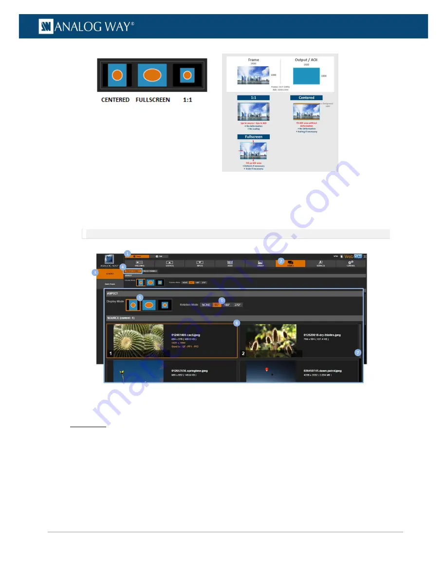
Select a ±90°

Rotation Mode

 if required. 

7.


If required, scroll the 

SOURCE

 window to navigate the frame library and locate the frame to use as 

preset frame 1 (or 2). 

8.


Finally, select the frame to use as preset frame 1 (or 2). 

NOTE:

 The 

SOURCE (current: #)

 number indicates the location of the selected frame in the library.   

To use a preset frame to transition through frame: 

Front Panel 

1.


Enter the 

CUSTOMIZE

 menu on the Front Panel interface. 

2.


Select 

Transition Effect

 to access the transition effect setup menu. 

3.


Select 

Type > FADE THROUGH FRAME

 to select the fade through frame transition type. 

4.


Select 

Preset Frame 1

 or

 Preset Frame 2

 to transition through preset frame 1 or 2, respectively. 

5.


If required, select

 Duration

 to adjust the transition effect duration. 


Summary of Contents for V701

Page 1: ... analogway com PROGRAMMER S GUIDE PROGRAMMER S GUIDE PROGRAMMER S GUIDE PROGRAMMER S GUIDE PROGRAMMER S GUIDE PROGRAMMER S GUIDE PROGRAMMER S GUIDE PROGRAMMER S GUIDE USER MANUAL VIO 4K Ref V701 USER MANUAL ...

Page 2: ... trademarks and logos are exclusive property of Analog Way and are protected by copyrights and other intellectual property rights 2016 Analog Way all rights reserved 10 2017 Consequently any representation and or reproduction in part or in full is prohibited and would be considered a violation of Analog Way s copyright and other intellectual property rights Visual representations diagrams photos i...

Page 3: ...on 9 1 9 Technical specifications 10 1 10 Environmental specification 10 2 Safety instructions 11 2 1 English 11 2 2 French 12 2 3 Italian 13 2 4 German 14 2 5 Spanish 15 3 Physical description 17 3 1 Front panel 17 3 2 Rear panel 18 4 Quick setup operation 19 4 1 Front panel control 19 4 1 1 Navigating the menus 19 4 1 2 Operating from the front panel 20 4 2 Web RCS interface 23 4 2 1 Connecting ...

Page 4: ...kups 47 5 9 Erasing the device memories 53 5 10 Updating the device 58 6 Output management 60 6 1 What is an output 60 6 2 Supported outputs formats and signals 60 6 2 1 Additional outputs supported with video expansion interfaces 62 6 3 Checking the output status 62 6 4 Setting up the output 64 6 4 1 Checking the plug status 64 6 4 2 Setting up the plug 66 6 4 3 Setting up the format 74 6 4 4 Adj...

Page 5: ...149 8 Frame management 150 8 1 What is a frame 150 8 2 Supported frame formats 150 8 3 Importing and exporting frames 150 8 4 Creating frame captures 154 8 5 Using frames as transitions 155 8 6 Using frames as quick frames 158 9 Screen management 163 9 1 What is a screen 163 9 2 Adjusting the view 163 9 3 Customizing the transition effect 166 9 4 Controlling the screen 168 1 0 Audio management 172...

Page 6: ... What is an EDID 216 13 2 Supported EDIDs 216 13 3 Managing EDIDs 217 1 4 HDCP support 225 14 1 HDCP detection 225 14 2 HDCP negotiation 225 14 3 Managing HDCP 226 1 5 Expansion interfaces 230 15 1 Audio expansion interfaces 230 15 1 1 Dante audio expansion interface 230 15 1 2 XLR audio expansion interface 230 15 2 Video cards 231 15 2 1 Extra output expansion interface 231 15 2 2 4K 60P expansio...

Page 7: ...ol and operate the conversion environment in a world of multiple possibilities You may for example set up your outputs before plugging in your sources or add additional cards to obtain a full 4K resolution display The all in one solution for any conversion User friendly and intuitive graphic interface Diverse selection of option cards for video and audio system expansion Flexible Audio Stereo swit...

Page 8: ...and scaling Live monitoring of sources and outputs on the 3 5 Color TFT LCD Display Output and screen patterns Crosshatch moving scalable output ID and other dynamic patterns New audio management 8 channels up to 96kHz Digital audio AES Audio Delay compensation up to 400ms Memory space for 2 uncompressed frames in 4K USB Host mass storage USB Device link Import export device configuration DVI HDMI...

Page 9: ...om live inputs outputs 1 7 Control Web RCS On board intuitive web based user interface TCP protocol and AMX Crestron drivers 1 8 Universal system for format conversion Upscale conversion Scaler Downscale conversion Scan converter Transcoder Coder Aspect ratios Multi format Analog Genlock Dynamic test patterns Pan Zoom functions Freeze Frame Aperture correction Advanced LED Wall functionalities Aud...

Page 10: ...ption card Supplied with 1 x Power supply cord 1 x Pair of front handles screws 1 x Rackmount kit 1 x Ethernet cross cable for device control 1 x MCO 5 pin connector 1 x Quick Start Guide including safety instructions All technical specifications and videos are available on analogway com NOTE Specifications subject to change without prior notice 1 10 Environmental specification General Cooling air...

Page 11: ...d with a detachable power cord To remove mains switch off the device and disconnect the power cord at appliance coupler Caution The power cord constitutes the only mean to completely disconnect the equipment from the main power Apply the following guidelines The equipment connected to the network must have a release system easily accessible and located outside the unit Unplug the power cord do not...

Page 12: ...n aucun cas cette liaison de terre ne devra être modifiée contournée ou supprimée Le raccordement des équipements à l alimentation principale doit être postérieur au disjoncteur de branchement de l installation électrique du bâtiment CORDON D ALIMENTATION Les appareils sont équipés d un cordon d alimentation détachable La mise hors tension se fait sur appareil éteint en débranchant ce cordon de l ...

Page 13: ...ura in prossimità o su superfici tessili suscettibili di ostruire il funzionamento della ventilazione Non installate l apparecchiatura in prossimità di sorgenti di calore come un radiatore o una fuoruscita d aria calda né in un posto esposto direttamente ai raggi del sole a polvere eccessiva a vibrazioni o a shock meccanici Ció potrebbe provocare un erroneo funzionamento e un incidente ALIMENTAZIO...

Page 14: ...eits und Betriebsanweisungen für einen späteren Gebrauch sicher aufbewahren Alle in den Unterlagen an dem Gerät und hier angegebenen Sicherheitsanweisungen einhalten ACHTUNG um jegliches Risiko eines Stromschlags oder Feuers zu vermeiden das Gerät nicht Regen Feuchtigkeit oder intensiven Wärmequellen aussetzen EINBAU Eine ausreichende Luftzufuhr sicherstellen um jegliche Überhitzung im Gerät zu ve...

Page 15: ...ebnahme von qualifiziertem Fachpersonal überprüfen lassen 2 5 Spanish Para un uso óptimo de este equipo lea las instrucciones de seguridad y operación antes de utilizarlo Conserve las instrucciones de seguridad y de funcionamiento para que pueda consultarlas posteriormente Respete todas las consignas indicadas en la documentación relacionadas con el producto y este documento CUIDADO Para prevenir ...

Page 16: ...atamente fuera de tensión Es peligroso hacer funcionar este aparato con un cable averiado ya que un cable dañado puede provocar un incendio o un choque eléctrico Verifique el estado del cable de alimentación de vez en cuando Póngase en contacto con su distribuidor o con el servicio de posventa si necesita cambiarlo CONEXIONES Todas las entradas y salidas a excepción de la entrada de alimentación s...

Page 17: ...PROGRAMMER S GUIDE PROGRAMMER S GUIDE PROGRAMMER S GUIDE PROGRAMMER S GUIDE USER MANUAL USER MANUAL USER MANUAL USER MANUAL USER MANUAL USER MANUAL USER MANUAL USER MANUAL USER MANUAL 3 1 Front panel 3 Physical description ...

Page 18: ...alogway com PROGRAMMER S GUIDE PROGRAMMER S GUIDE PROGRAMMER S GUIDE PROGRAMMER S GUIDE USER MANUAL USER MANUAL USER MANUAL USER MANUAL USER MANUAL USER MANUAL USER MANUAL USER MANUAL USER MANUAL 3 2 Rear panel ...

Page 19: ...access the front panel menu tree Front panel menus on LCD display You can use the front panel control knob and the ENTER and EXIT MENU buttons to navigate through the menus and adjust your setup Rotate the control knob clockwise or anti clockwise to navigate through menus scroll a list increase or decrease a value Press the ENTER button to validate a selection enter a menu choose an item from a li...

Page 20: ...s like color temperature brightness and contrast to truly fine tune your output image INPUT MENU Enter the INPUTS menu to have an overview of all your inputs and their status Select AUTOSET ALL to launch the automatic detection of all plugs of all inputs Input settings Select an input to set up the input individually Enter the Plug Settings menu to select the type of input signal by plug enable or...

Page 21: ...f your input and view settings and load them readily at runtime TIP Double click on an input selection button to access the input setup and view settings menu SOURCE CONTROL Freeze the output and Monitor inputs and outputs on the front panel LCD display Customize the Transition Type and the Transition Duration to smoothly transition between sources Use Frames to transition through frame or activat...

Page 22: ...22 www analogway com PROGRAMMER S GUIDE PROGRAMMER S GUIDE PROGRAMMER S GUIDE PROGRAMMER S GUIDE PROGRAMMER S GUIDE PROGRAMMER S GUIDE PROGRAMMER S GUIDE PROGRAMMER S GUIDE USER MANUAL ...

Page 23: ...tion to connect You can easily connect to the Web RCS client of your VIO 4K unit using a standard LAN network AUTOMATIC LAN SETUP To connect to the Web RCS of your VIO 4K using a standard LAN network 1 Connect your computer to the VIO 4K using the provided Ethernet cable 2 On your computer open a web browser that supports Flash player 3 In this web browser enter the IP address of your VIO 4K displ...

Page 24: ...ubnet as your VIO 4K for example IP address 192 168 2 16 Netmask 255 255 255 0 3 Confirm the new settings You should be able to connect now open a web browser and type in the unit IP address displayed in the front panel LCD screen to connect CONNECTION ESTABLISHED Once the connection has been established the Web RCS interface will load into your web browser The 2 icons at the bottom right corner o...

Page 25: ... Ram 200Mb of free space 100Mb Network adaptor or above 1920x1080 optimized screen resolution 1366x768 as the minimum screen resolution Operating system Windows XP SP3 or above Mac OS v10 7 or above Ubuntu v10 or above Linux OS 11 or above Web browser support IE v10 or above Chrome v32 or above Firefox v22 or above Safari v6 or above Opera v10 or above NOTE The Web RCS has been optimized for Chrom...

Page 26: ...vice mode connection 2 Connect your computer to the VIO 4K 1 Plug in the USB type B connector to the front panel USB device port 2 Plug in the USB type A connector to your computer USB port 3 Copy the Ethernet over USB driver to your computer 1 Open the VIO 4K_USB driver 2 Go to the Drivers Windows folder and select XP 3 Copy the file AW_VIO4K_EtherOverUsb inf to your computer 4 Enable the Etherne...

Page 27: ... select your platform 3 Double click on AW_VIO4K_Driver_EtherOverUSB exe to start the driver installation 4 Accept to install a Network Card type driver if asked during the installation 4 Enable the Ethernet over USB device connection 1 Go to the CONTROL USB Device menu on the front panel interface 2 Select Connection Mode ETHERNET to enabled the Ethernet over USB connection 5 Connect to the Web R...

Page 28: ...hoose Let me pick from a list of device drivers on my computer 6 By default the Show compatible hardware option is enabled and allows you to select two drivers USB serial peripheral VIO4K USB Ethernet RNDIS Gadget 7 Select the VIO4K USB Ethernet RNDIS Gadget driver and click Next NOTE You will need to install the driver if the VIO4K USB Ethernet RNDIS gadget is not available The driver is now asso...

Page 29: ...r and type in the IP address of your VIO 4K unit displayed in the front panel LCD screen to access the Web RCS interface With the Web RCS interface loaded into your web browser you can start operating your VIO 4K unit from a PC or tablet via LAN or via USB SETUP MENU Click on the Setup tab to start setting up your device Adjust the active area of your display in the output format AOI and the scree...

Page 30: ...the Edit tab to start putting it all together in the screen Select the input to display on the output Set up the View for each input Create Presets of your input and view settings Freeze and control the output Customize the transition effect when switching sources Manage the screen layout TIP Use Presets to save all your screen configurations and quickly recall them at runtime TIP Carry on reading...

Page 31: ...ivate and deactivate using the Front Panel ON OFF button To send the device to standby 1 Press the VIO 4K front panel ON OFF button 2 When asked for confirmation select YES to send the device to standby or NO to cancel the action NOTE The VIO 4K will start up in standby mode if you shut down the device with the back to standby power loss function enabled SEE Alternative method below for more detai...

Page 32: ...on the Front Panel interface 2 Scroll down and select Front Panel to access the front panel settings menu 3 Select LCD Brightness and rotate the control knob left or right to adjust the brightness of the front panel LCD display Select ENTER to save the new value Select EXIT MENU to restore the last saved value Web RCS 1 Go to the Setup menu on the Web RCS interface 2 Click on the CONTROL tab to ac...

Page 33: ...ts 5 Minutes Standby after 5 minutes of inactivity 15 Minutes Standby after 15 minutes of inactivity 30 Minutes Standby after 30 minutes of inactivity 1 Hour Standby after 1 hour of inactivity DISABLE No standby Web RCS 1 Go to the Setup menu on the Web RCS interface 2 Click on the CONTROL tab to access the device settings and control functions 3 In the left side toolbar select Front Panel to acce...

Page 34: ...to the Setup menu on the Web RCS interface 2 Click on the CONTROL tab to access the device settings and control functions 3 In the left side toolbar select Front Panel to access the front panel settings page 4 Uncheck the Timeout check box to stay on the current menu page whatever the timeout To adjust the key buttons brightness Front Panel 1 Enter the CONTROL menu on the Front Panel interface 2 S...

Page 35: ...Panel to access the front panel settings menu 3 Select Front panel locking to change the front panel key locking mode List of possible front panel key locking modes NONE Lock no front panel button all enabled front panel key buttons will be available ONLY MENUS Lock the front panel navigation buttons only INPUT SELECTION buttons and SHORTCUT buttons will remain available MENUS KEYBOARD Lock all th...

Page 36: ...hich no valid signal has been detected will be disabled Inputs without signal will still be available for selection via the Web RCS interface and all input settings will remain available from both the Front Panel and the Web RCS interfaces Web RCS 1 Go to the Setup menu on the Web RCS interface 2 Click on the CONTROL tab to access the device settings and control functions 3 In the left side toolba...

Page 37: ... menu 3 Check the Obtain IP via DHCP check box to enable DHCP automatic IP detection mode 4 Select Apply to save and apply the new settings upon prompt select YES to confirm or NO to cancel and restore the last saved settings TIP Select Restore to Default Setup whenever required to restore the LAN settings default values Web RCS Not recommended All currently connected Web RCS clients will be disco...

Page 38: ...ings upon prompt select YES to confirm or NO to cancel and restore the last saved settings TIP Select Restore to Default Setup whenever required to restore the LAN settings default values Web RCS Not recommended All currently connected Web RCS clients will be disconnected 1 Go to the Setup menu on the Web RCS interface 2 Click on the CONTROL tab to access the device settings and control functions ...

Page 39: ...a USB SEE Connecting to the Web RCS USB for more information By default the USB device connection is disabled on the VIO 4K You can enable it to control your VIO 4K unit from a PC or tablet via USB To enable the mass storage USB device connection Information It is strongly recommended to read the section Connecting to the Web RCS USB before you start Front Panel 1 Enter the CONTROL menu on the Fro...

Page 40: ...box to enable the USB device interface connection 5 Click on MASS STORAGE to connect to the unit as a mass storage device To enable the Ethernet over USB device connection Information It is strongly recommended to read the section Connecting to the Web RCS USB before you start Front Panel 1 Enter the CONTROL menu on the Front Panel interface 2 Select USB Device 3 Uncheck the Disable Interface chec...

Page 41: ... the USB connection Information It is strongly recommended to read the section Connecting to the Web RCS USB before you start Front Panel 1 Enter the CONTROL menu on the Front Panel interface 2 Select USB Device 3 Uncheck the Disable Interface check box to enable the USB device interface connection 4 Select Connection Mode ETHERNET to check the Ethernet over USB connection Connection status Ethern...

Page 42: ...rks like the front panel switch When the device is on closing the switch requests the device to power down If the switch remains closed more than 5 seconds a forced power down is performed When the device is off closing the switch turns on the device NOTE Only a wire with a simple switch can be connected No voltage should be applied on on off pins GPO pins are optically isolated MOSFET working as ...

Page 43: ...PO Front Panel 1 Enter the CONTROL menu on the Front Panel interface 2 Select GPO Settings to access the GPOs settings menu 3 Select GPO 1 or GPO 2 to edit the GPO 1 or 2 parameters 4 Select Mode and rotate the control knob left or right to choose the mode for GPO 1 or 2 Press the ENTER key to validate your selection Press the EXIT MENU key to exit without saving List of possible GPO modes Require...

Page 44: ...e VIO 4K for the first time you can reset the device to factory settings as is out of the box to start enjoying the unit as a brand new device You can also simply reset the unit to its configuration default values to keep the Frame Library and the current configuration of your Network Web RCS and Link settings FORCE OPEN STATE Open by user action FORCE CLOSED STATE Closed by user action CLOSED IF ...

Page 45: ...reset this action is irreversible Select NO to cancel the action NOTE The unit will reboot itself once the reset is complete Web RCS 1 Go to the Setup menu on the Web RCS interface 2 Click on the CONTROL tab to access the device settings and control functions 3 In the left side toolbar select Factory Reset to access the resets page 4 Under Configuration Default Value click on the Start button Clic...

Page 46: ...e reset this action is irreversible Select NO to cancel the action NOTE The unit will reboot itself once the reset is complete Web RCS 1 Go to the Setup menu on the Web RCS interface 2 Click on the CONTROL tab to access the device settings and control functions 3 In the left side toolbar select Factory Reset to access the resets page 4 Under Factory Reset Out of the Box click on the Start button S...

Page 47: ...tion Front Panel configuration Communication interfaces Communication interfaces Input parameters Input parameters Output parameters Output parameters Audio parameters Audio parameters GPO parameters GPO parameters Frames library All the frame library WebRCS settings WebRCS settings Current preset parameters Current preset parameters Custom formats library Custom format library Preset and view lib...

Page 48: ... Output parameters Audio parameters Audio parameters GPO parameters GPO parameters Frames library All the frame library WebRCS settings WebRCS settings Current preset parameters Current preset parameters Custom formats library Custom format library Preset and view library Preset and view library EDID library EDID library Input EDID Input EDID Device logs Device logs All All categories 5 Click on G...

Page 49: ...nel configuration Front Panel configuration Communication interfaces Communication interfaces Input parameters Input parameters Output parameters Output parameters Audio parameters Audio parameters GPO parameters GPO parameters Frames library All the frame library WebRCS settings WebRCS settings Current preset parameters Current preset parameters Custom formats library Custom format library Preset...

Page 50: ...meters Input parameters Output parameters Output parameters Audio parameters Audio parameters GPO parameters GPO parameters Frames library All the frame library WebRCS settings WebRCS settings Current preset parameters Current preset parameters Custom formats library Custom format library Preset and view library Preset and view library EDID library EDID library Input EDID Input EDID Device logs De...

Page 51: ...age SEE also Saving a configuration to the device storage 4 Use the USB device browser to select the configuration to import TIP Use the ENTER and EXIT MENU keys to navigate through folders 5 Select the categories to import if required and then select Import Config Available import categories include General configuration General configuration Front Panel configuration Front Panel configuration Co...

Page 52: ...Open 7 In the Upload configuration file window click on the Upload button to start the upload process 8 Once the upload is complete select the categories to import Available import categories include General configuration General configuration Front Panel configuration Front Panel configuration Communication interfaces Communication interfaces Input parameters Input parameters Output parameters Ou...

Page 53: ...evice SEE also Saving a configuration to the device storage The device memories are settings that have been saved to the device either automatically like input settings memories or by user action like frames and user EDIDs or preset view and custom format memories To erase all input settings memories Front Panel 1 Enter the CONTROL menu on the Front Panel interface 2 Scroll down and select Reset E...

Page 54: ...e to cancel the action To erase all view memories Front Panel 1 Enter the CONTROL menu on the Front Panel interface 2 Scroll down and select Reset Erase to access the reset and erase menu 3 Select Reset View Memories to start clearing up the view bank Select YES to confirm this action is irreversible Select NO to cancel Web RCS 1 Go to the Setup menu on the Web RCS interface 2 Click on the CONTROL...

Page 55: ...ess the reset and erase menu 3 Select Reset Preset Memories to start clearing up the preset bank Select YES to confirm this action is irreversible Select NO to cancel Web RCS 1 Go to the Setup menu on the Web RCS interface 2 Click on the CONTROL tab to access the device settings and control functions 3 In the left side toolbar select Erase Memories to access the erase memories page 4 Under Erase P...

Page 56: ...el Web RCS 1 Go to the Setup menu on the Web RCS interface 2 Click on the CONTROL tab to access the device settings and control functions 3 In the left side toolbar select Erase Memories to access the erase memories page 4 Under Erase Library Images click on the Start button Click again to confirm this action is irreversible Click elsewhere to cancel the action To erase all custom format memories ...

Page 57: ... irreversible Click elsewhere to cancel the action To erase all user EDIDs Front Panel 1 Enter the CONTROL menu on the Front Panel interface 2 Scroll down and select Reset Erase to access the reset and erase menu 3 Select Erase EDID Library to start clearing up the user EDID bank Select YES to confirm this action is irreversible Select NO to cancel Web RCS 1 Go to the Setup menu on the Web RCS int...

Page 58: ... can update your VIO 4K unit to enjoy the latest firmware on the device The updater release information includes Updater version Executable file name Creation date Version and Checksums of the different programmable components List of the implemented functional evolutions evolution ID and title in English List of the corrected bugs bug ID and bug title in English 5 10 Updating the device ...

Page 59: ...it until the device is properly recognized and proceed as explained below 1 Enter the CONTROL menu on the Front Panel interface 2 Select USB Host 3 Select Scan For Updater 4 Select Confirm to start the update Web RCS NOTE Back up your settings and download the latest firmware from http www analogway com before you start 1 Go to the Setup menu on the Web RCS interface 2 Click on the SERVICES tab to...

Page 60: ...llowing plugs The following table provides information on the list of supported output formats and signals Plug type Formats Signals Universal Analog HD15 SDTV YCbCr ITU R BT 601 EDTV YCbCr ITU R BT 601 HDTV YCbCr ITU R BT 709 Computer RGBHV RGBs RGsB DVI D Dual Link EDTV YCbCr ITU R BT 601 RGB Full scale 0 255 RGB Limited scale 16 235 HDTV YCbCr ITU R BT 709 RGB Full scale 0 255 RGB Limited scale...

Page 61: ...e 0 255 RGB Limited scale 16 235 HDTV YCbCr ITU R BT 709 RGB Full scale 0 255 RGB Limited scale 16 235 UHDTV 4K up to 30Hz YCbCr ITU R BT 709 RGB Full scale 0 255 RGB Limited scale 16 235 Computer YCbCr ITU R BT 601 RGB Full scale 0 255 RGB Limited scale 16 235 3G SDI SDTV SMPTE 259M C YCbCr ITU R BT 601 4 2 2 HDTV SMPTE ST296 720p YCbCr ITU R BT 709 4 2 2 SMPTE 274M 1080i 1080p YCbCr ITU R BT 709...

Page 62: ...atus provides information on the current output configuration Available output status information includes Format Mode Current mode used to set up the format Possible output format modes include INTERNAL REF Internal reference format mode AUTO EDID FORMAT Automatic format mode based on EDID FRAMELOCK Framelock format mode GENLOCK Genlock format mode Format Currently applied format Rotation Current...

Page 63: ...D BY DISPLAY Plug is disabled because the display is not compatible with the format parameters To check the status of your outputs Front Panel 1 Enter the OUTPUTS menu on the Front Panel interface 2 Select STANDARD OUTPUT to access the standard output setup menu 3 Select Output Status to check the output status information Alternative method 1 Enter the SUMMARY menu on the Front Panel interface 2 ...

Page 64: ...ontrol the final rendering of the output in the screen The output plug status provides information on the current configuration of your output plugs Available plug status information includes Status Output plug status List of possible status for each plug include NOT AVAILABLE Plug is not available for this output ACTIVE Plug is active for this output ACTIVE WARNING EDID INVALID Plug is active but...

Page 65: ... 2 2 ITU R BT 601 or ITU R BT 709 Color Depth Current color depth status List of possible signal color depths 18 BITS 6 bpc 18 bits for a pixel 6 bits for each color 24 BITS 8 bpc 24 bits for a pixel 8 bits for each color 30 BITS 10 bpc 30 bits for a pixel 10 bits for each color HDCP Status Current HDCP status for the plug Monitor Current monitor name if detected on the plug HDMI Mode Current HDMI...

Page 66: ...w active plugs only 5 Check the plug status information right below each output plug You can optimize the output by setting up each output plug You can select the signal type on a plug for example enable disable HDCP detection on the plug force the DVI mode of HDMI plugs choose the audio mode of SDI optical plugs enable the loop mode of HDMI DVI and analog plugs etc Both the signal type and the co...

Page 67: ...gnal 0 700mV RGsB RGB signal with synchro on green SOG RGBs RGB signal with a TTL composite synchro RGBHV RGB signal with separate TTL H V synchro Web RCS 1 Go to the Setup menu on the Web RCS interface 2 Click on the OUTPUTS tab to access the outputs setup page 3 In the left side toolbar select STANDARD OUTPUT to access the standard output setup page 4 Disable the Hide all plugs button if require...

Page 68: ... digital plugs only Available color spaces include AUTO Automatic color space selection RGB FULL 0 255 RGB Full scale 0 255 RGB LIMITED 16 235 RGB Limited scale 16 235 YCbCr 4 4 4 YCbCr 4 4 4 ITU R BT 601 or ITU R BT 709 YCbCr 4 2 2 YCbCr 4 2 2 ITU R BT 601 or ITU R BT 709 Web RCS 1 Go to the Setup menu on the Web RCS interface 2 Click on the OUTPUTS tab to access the outputs setup page 3 In the l...

Page 69: ... the output 4 Select a plug to access the selected plug setup menu 5 Select Color Depth and choose the color space for the plug digital plugs only Web RCS 1 Go to the Setup menu on the Web RCS interface 2 Click on the OUTPUTS tab to access the outputs setup page 3 In the left side toolbar select STANDARD OUTPUT to access the standard output setup page 4 Disable the Hide all plugs button if require...

Page 70: ...ss the standard output setup menu 3 Select Plug Settings to access the plug setup menu for the output 4 Select an HDMI plug to access the HDMI plug setup menu 5 Check the Force DVI Mode check box to force the DVI mode on the plug no audio will be transmitted Web RCS 1 Go to the Setup menu on the Web RCS interface 2 Click on the OUTPUTS tab to access the outputs setup page 3 In the left side toolba...

Page 71: ...EL A Transport in 1 x 3G Level A coax LEVEL B Transport in 1 x 3G Level B coax 6 If required select the SDI audio output mode SEE also Audio management SDI audio NOTE The chosen 3G transport and audio modes affect both SDI and OPTICAL plugs Web RCS 1 Go to the Setup menu on the Web RCS interface 2 Click on the OUTPUTS tab to access the outputs setup page 3 In the left side toolbar select STANDARD ...

Page 72: ...e status on the output plug Non HDCP output peripheral Output is blackened even if HDCP is enabled on the output plug Only on video plugs standard that support HDCP HDMI DisplayPort DVI By enabling and disabling HDCP you can thus relatively control the whole HDCP stream Input control With HDCP enabled default the HDCP negotiation is maintained even if the DVI HDMI or DisplayPort plug is not the cu...

Page 73: ...led all screens are seen as non HDCP compliant TIP Go to the CUSTOMIZE menu and select HDCP Manager to manage HDCP on all output plugs Web RCS 1 Go to the Setup menu on the Web RCS interface 2 Click on the OUTPUTS tab to access the outputs setup page 3 In the left side toolbar select STANDARD OUTPUT to access the standard output setup page 4 Disable the Hide all plugs button if required to show th...

Page 74: ...t mode The Auto EDID format mode selects an output plug and applies the preferred format read in its EDID to the output format If the plug EDID is not available or corrupted the applied output format is the one determined in the format and rate menus Framelock mode The Framelock video mode allows you to choose a 0 5x 1x or 2x rate mode while using the output or one of its inputs as a video referen...

Page 75: ...40x480 4 3 VGA 800x480 15 9 WVGA DMT 800x600 4 3 SVGA DMT 848x480 16 9 WVGA DMT 1024x768 4 3 XGA 1088x817 4 3 DMT 1152x864 4 3 DMT 1280x720 16 9 720p DMT 1280x768 15 9 WXGA DMT 1280x800 16 9 WXGA2 DMT 1280x960 4 3 DMT 1280x1024 5 4 SXGA DMT 1360x768 16 9 DILA 1360x1024 4 3 DMT 1366x768 16 9 WXGA 1366x800 15 9 WXGA DMT 1400x1050 4 3 SXGAP DMT 1440x900 16 10 900p DMT 1440x1080 4 3 DMT 1600x900 16 9 ...

Page 76: ...DTV 1080i HDTV 1080sF HDTV 1080p DCDM 2K 2048x1080 UHDTV 2160p 3840x2160 DCDM 4K 4096x2160 DMT 640x480 4 3 VGA 800x480 15 9 WVGA DMT 800x600 4 3 SVGA DMT 848x480 16 9 WVGA DMT 1024x768 4 3 XGA 1088x817 4 3 DMT 1152x864 4 3 DMT 1280x720 16 9 720p DMT 1280x768 15 9 WXGA DMT 1280x800 16 9 WXGA2 DMT 1280x960 4 3 DMT 1280x1024 5 4 SXGA DMT 1360x768 16 9 DILA 1360x1024 4 3 DMT 1366x768 16 9 WXGA 1366x80...

Page 77: ... preferred format 5 Select the plug used for auto EDID and wait for the Format generation in progress screen 6 Once the setup is complete press the EXIT MENU button to return to the output setup menu Web RCS 1 Go to the Setup menu on the Web RCS interface 2 Click on the OUTPUTS tab to access the outputs setup page 3 In the left side toolbar select STANDARD OUTPUT to access the standard output setu...

Page 78: ... MODE x0 5 The reference rate is the reference signal rate divide by 2 two times slower MODE x1 The reference rate is the reference signal rate MODE x2 The reference rate is the reference signal rate multiply by 2 two times faster Rate mode restrictions The product Input Reference Rate x Rate Factor must be 23 97 Hz and 120 Hz 7 Select the Framelock video Reference NOTE All inputs can be used as F...

Page 79: ...ith the Framelock video mode 7 Click on Reference and select the Framelock video reference NOTE All inputs can be used as Framelock reference Available input references for framelock include INPUT 1 Framelock on DisplayPort input INPUT 2 Framelock on HDMI input on back panel INPUT 3 Framelock on HD15 input INPUT 4 Framelock on Optical input INPUT 5 Framelock on SDI input INPUT 6 Framelock on DVI D...

Page 80: ...screen to check the new format settings 7 Once the setup is complete press the EXIT MENU button to return to the output setup menu TIP Go to the output setup menu and select Genlock Tune to adjust the vertical and horizontal offsets to apply to the output signal Offset H Offset in pixels ratio of 1 line to apply to the output signal Offset V Offset in lines ratio of 1 frame to apply to the output ...

Page 81: ...nal Offset V Offset in lines ratio of 1 frame to apply to the output signal 7 Select APPLY to save and apply the new settings TIP Select Genlock Ref In the left side toolbar and click on Overload Detected Format to specify the format to use on the Genlock reference input SEE Using the Genlock reference Related topics Using the Genlock reference The Area of Interest AOI defines the active area of y...

Page 82: ...up menu 3 Select Area of Interest to access the AOI setup menu 4 Check the Fit Format Resolution check box to automatically fit the AOI to the output format 5 If required adjust the Overscan Compensation as percentage of the output format size Web RCS 1 Go to the Setup menu on the Web RCS interface 2 Click on the PRECONFIG tab to access the setup assistant 3 If the Screens page is active click on ...

Page 83: ...rs H Position AOI vertical start offset compared to the output format in pixels H Size AOI horizontal size in pixels V Position AOI vertical start offset compared to the output format in pixels V Size AOI vertical size in pixels TIP Use the Reset command if required to reset the AOI size and position to its default values Web RCS 1 Go to the Setup menu on the Web RCS interface 2 Click on the PRECO...

Page 84: ...Rotating the output content can be very useful to adapt to a landscape display installed with a portrait orientation for example To rotate the output content Front Panel 1 Enter the OUTPUTS menu on the Front Panel interface 2 Select STANDARD OUTPUT to access the standard output setup menu 3 Select Rotation to select the 90 rotation of the output content Web RCS 1 Go to the Setup menu on the Web RC...

Page 85: ... 1 Enter the OUTPUTS menu on the Front Panel interface 2 Select STANDARD OUTPUT to access the standard output setup menu 3 Select Image Correction to access the output image colorimetry adjustments menu 4 Select a colorimetry adjustment to adjust the output image Web RCS 1 Go to the Setup menu on the Web RCS interface 2 Click on the OUTPUTS tab to access the outputs setup page 3 In the left side t...

Page 86: ...1 Enter the OUTPUTS menu on the Front Panel interface 2 Select STANDARD OUTPUT to access the standard output setup menu 3 Select Image Correction to access the output image colorimetry adjustments menu 4 Select Reset to reset all colorimetry adjustments Web RCS 1 Go to the Setup menu on the Web RCS interface 2 Click on the OUTPUTS tab to access the outputs setup page 3 In the left side toolbar sel...

Page 87: ...ORIZONTAL COLOR BAR Horizontal color bar GRID 16x16 Grid composed of 16 rectangles in height and width GRID 32x32 Grid composed of 32 rectangles in height and width GRID CUSTOM Grid composed of user custom rectangle size SMPTE SMPTE HORIZONTAL BURST Horizontal burst VERTICAL BURST Vertical burst VERTICAL GRADIENT Vertical gradient HORIZONTAL GRADIENT Horizontal gradient CROSSHATCH Crosshatch CHECK...

Page 88: ...ments on the pattern uncheck to enable Motion Check to enable a live movement on the pattern Pattern Area Area where the pattern applies Possible pattern areas include FORMAT Fit pattern in all format resolution AOI Fit pattern in all AOI Format Raster Box Check to display a dotted line all around the format AOI Raster Box Check to display a dotted line all around the AOI area Web RCS 1 Go to the ...

Page 89: ...UT to access the standard output setup menu 3 Select Pattern to access the output pattern setup menu NOTE You can also use the front panel Test Pattern key to access the output pattern setup menu directly 4 Check the Inhibit Output Pattern check box to hide the pattern NOTE You can disable pattern display whenever required by checking the Inhibit Output Pattern check box All pattern adjustments wi...

Page 90: ...rn display Related topics Checking the output status Creating custom formats Using the Genlock reference You can monitor the output both from the Front Panel and the Web RCS interfaces Monitoring the output will allow you to check your output adjustments before the connection setup is complete for example To monitor the output Front Panel 1 Press the Monitor button in the Front Panel interface 2 S...

Page 91: ...he Web RCS interface 2 Select the MON STREAM tab to access the monitoring page 3 Go to the Properties toolbar on right hand side 4 Under Setup Source scroll down and select STANDARD OUTPUT 5 If required select the Quality of the monitoring stream TIP Use the Play and Fullscreen buttons at the bottom of the monitoring screen to control the monitoring stream playback and display size NOTE You can al...

Page 92: ...e Edit menu on the Web RCS interface 2 Click on the Freeze button at the bottom of the screen to freeze the output click again or select another input to unfreeze SEE Creating frame captures The Genlock input can be used as a reference and a rate multiplier to set up the output format SEE Setting up the format If the Genlock input allows it you can further specify the format to use on the Genlock ...

Page 93: ... FORMAT 4 Scroll down the list of formats detected on the Genlock input and select the format to use on the Genlock reference input Web RCS 1 Go to the Setup menu on the Web RCS interface 2 Click on the OUTPUTS tab to access the outputs setup page 3 In the left side toolbar select Genlock Ref to access the Genlock input settings page 4 Under Overload Detected Format select the format to use on the...

Page 94: ...lug thus becomes an unscaled loop of the selected input and it is no longer available as a standard scaled output HDMI and DVI loops share the same hardware resources This means both the HDMI and DVI output plugs will be affected when enabling loop mode and will display the same looped input signal On SDI plugs the loop capability is directly implemented in the hardware SEE Rear panel description ...

Page 95: ...interface 2 Click on the OUTPUTS tab to access the outputs setup page 3 In the left side toolbar select STANDARD OUTPUT to access the standard output setup page 4 Disable the Hide all plugs button if required to show the output plugs 5 Click on the Show plugs settings button to access the plug settings for each output plug 6 Locate the plug to set up 7 Check uncheck the Loop Mode box to enable dis...

Page 96: ... optical On the VIO 4K each plug receives only one type of signal at a time and each input has only one active plug whose content can be displayed on the output SEE also Audio inputs The following table provides information on the list of supported input formats and signals for each plug Standard Size DisplayPo rt 1 2 HDMI 1 4 3G SDI 3G SDI SFP Slot Dual Link DVI D HD 15 480i 525 480i Yes Yes Yes ...

Page 97: ...Yes SXGA 1280x1024 Yes Yes No No Yes Yes SWXGA 1360x768 Yes Yes No No Yes Yes 1366x768 1366x768 Yes Yes No No Yes Yes SWXGA 1366x800 Yes Yes No No Yes Yes 1360x1024 1360x1024 Yes Yes No No Yes Yes DILA4 3 1364x1024 Yes Yes No No Yes Yes SXGA 1400x1050 Yes Yes No No Yes Yes 900p RGB 1440x900 Yes Yes No No Yes Yes 1600x900 1600x900 Yes Yes No No Yes Yes UXGA 1600x1200 Yes Yes No No Yes Yes WSXGA 168...

Page 98: ...SDTV 576i SDTV 576i EDTV 480p EDTV 480p EDTV 576p EDTV 576p HDTV 720p HDTV 720p HDTV 1035i HDTV 1035i HDTV 1080i HDTV 1080i HDTV 1080p HDTV 1080p PROJECTOR 1200p Projector specific 1200p CINEMA 2K CINEMA 2048x1080 UHDTV 2160p UHDTV 3840x2160 CINEMA 4K CINEMA 4096x2160 CEA 861 240p CEA861 720x240p CEA 861 288p CEA861 720x288p COMPUTER 640x350 CPU 640x350 COMPUTER 640x400 CPU 640x400 COMPUTER 720x40...

Page 99: ...52 CPU QWXGA COMPUTER 1600x1200 CPU UXGA COMPUTER 1920x1200 CPU WUXGA COMPUTER 1792x1344 CPU 1792x1344 COMPUTER 1856x1392 CPU 1856x1392 COMPUTER 1920x1440 CPU 1920x1440 COMPUTER 2560x1440 CPU WQHD COMPUTER 3440x1440 CPU 3440x1440 COMPUTER 2048x1536 CPU QXGA COMPUTER 2560x1600 CPU WQXGA COMPUTER 2560x2048 CPU 2560x2048 COMPUTER 1920x2160 CPU 1920x2160 COMPUTER 2048x2160 CPU 2048x2160 COMPUTER 4096x...

Page 100: ... Web RCS interface 2 Click on the INPUTS tab to access the inputs setup page 3 In the left side toolbar select General to access the general inputs setup page 4 Check the input status next to each input preview window You can request the automatic setup of all inputs The automatic request will scan all inputs and plugs and automatically select the active plugs for each input NOTE You can also indi...

Page 101: ...porarily Select NO to cancel the request Web RCS 1 Go to the Setup menu on the Web RCS interface 2 Click on the INPUTS tab to access the inputs setup page 3 In the left side toolbar select General to access the general inputs setup page 4 Click on the Autoset All button to request the automatic setup of all plugs of all inputs TIP On the Front Panel interface double click on an input selection key...

Page 102: ...y flicker Input plugs may change temporarily Front Panel 1 Enter the INPUTS menu on the Front Panel interface 2 Scroll down and select an input to access the selected input setup menu TIP Double click on an INPUT SELECTION button to shortcut to the input setup menu directly 3 Select Autoset Input to request the automatic setup of the input plug Select YES to confirm if displayed the input may flic...

Page 103: ...ro SOG converted to grey level COMPUTER HV RGB signal with separate TTL H V synchro COMPUTER TTL COMPOSITE RGB signal with a TTL composite synchro COMPUTER ANA COMPOSITE RGB signal with an analog composite synchro List of possible input color spaces digital plugs AUTO Automatic color space selection YUV YUV YCbCr ITU R BT 601 or YCbCr BT 709 RGB FULL 0 255 RGB Full scale 0 255 RGB LIMITED 16 235 R...

Page 104: ...mented frame Settings Memory Slot Memory slot used for the input settings 0 means that no slot is used or that default settings are used HDMI DVI plugs HDMI mode HDMI mode status in DVI mode no audio can be transmitted All except HD15 Repeat Coefficient DVI and HDMI signals only Repetition coefficient for pixel Color Space Color space of the signal List of possible input color spaces digital plugs...

Page 105: ...12G UHD SD 12G SDI standard Available with the optional video card To check the status of an input plug Front Panel 1 Enter the INPUTS menu on the Front Panel interface 2 Scroll down and select an input to access the selected input setup menu TIP Double click on an INPUT SELECTION button to shortcut to the input setup menu directly 3 Select the plug settings to access the input plug settings menu ...

Page 106: ...ype to use on the plug To auto detect the signal type on a plug NOTE If displayed the input may flicker The input plug may change temporarily Front Panel 1 Enter the INPUTS menu on the Front Panel interface 2 Scroll down and select an input to access the selected input setup menu TIP Double click on an INPUT SELECTION button to shortcut to the input setup menu directly 3 Select Plug Settings to ac...

Page 107: ...ings to access the input plug settings menu 4 Select Type to select the signal type color space for the plug List of possible input signal types analog plugs SDTV COMPOSITE Composite signal 0 700mV SDTV YC Y C signal 0 700mV VIDEO RGBS RGBs signal with a TTL composite synchro only video format VIDEO RGSB RGB signal with synchro on green SOG only video format VIDEO YUV YUV signal 0 700mV COMPUTER S...

Page 108: ... 0 700mV SDTV YC Y C signal 0 700mV VIDEO RGBS RGBs signal with a TTL composite synchro only video format VIDEO RGSB RGB signal with synchro on green SOG only video format VIDEO YUV YUV signal 0 700mV COMPUTER SOG RGB signal with synchro on green SOG COMPUTER BW Only Green signal with synchro SOG converted to grey level COMPUTER HV RGB signal with separate TTL H V synchro COMPUTER TTL COMPOSITE RG...

Page 109: ...o shortcut to the input setup menu directly 3 Select the plug settings to access the input plug settings menu 4 Uncheck the Enabled check box to disable the plug check to enable NOTE Disabling the plug will also disable the sources connected to the plug and the input itself will no longer be available for selection Web RCS 1 Go to the Setup menu on the Web RCS interface 2 Click on the INPUTS tab t...

Page 110: ... click on an INPUT SELECTION button to shortcut to the input setup menu directly 3 Check the Force Black check box to force the input sources connected to the plug to output to black uncheck to output normally Web RCS 1 Go to the Setup menu on the Web RCS interface 2 Click on the INPUTS tab to access the inputs setup page 3 In the left side toolbar select an input to access the selected input setu...

Page 111: ...8 50Hz 1024x768 60Hz 1024x768 70Hz 1024x768 75Hz 1024x768 85Hz 1024x768 120Hz REDUCED BLANKING 1088x817 50Hz 1088x817 60Hz 1152x864 50Hz 1152x864 60Hz 1152x864 75Hz 1280x600 50Hz 1280x600 60Hz 1280x720 23 976Hz 1280x720 24Hz 1280x720 25Hz 1280x720 29 97Hz 1280x720 30Hz 1280x720 50Hz 1280x720 59 94Hz 1280x720 60Hz 1280x720 100Hz 1280x720 119 88Hz 1280x720 120Hz 1280x768 50Hz 1280x768 60Hz REDUCED B...

Page 112: ...ING 1680x720 23 976Hz 1680x720 24Hz 1680x720 25Hz 1680x720 29 97Hz 1680x720 30Hz 1680x720 50Hz 1680x720 59 94Hz 1680x720 60Hz 1680x720 100Hz 1680x720 119 88Hz 1680x720 120Hz 1680x1050 50Hz 1680x1050 60Hz REDUCED BLANKING 1680x1050 60Hz 1680x1050 75Hz 1680x1050 85Hz 1680x1050 120Hz REDUCED BLANKING 1792x1344 50Hz 1792x1344 60Hz 1856x1392 50Hz 1856x1392 60Hz 1920x1080 23 976Hz 1920x1080 24Hz 1920x10...

Page 113: ...D BLANKING 2560x2048 50Hz 2560x2048 60Hz REDUCED BLANKING 3440x1440 50Hz 3440x1440 60Hz REDUCED BLANKING 3840x2160 23 976Hz 3840x2160 24Hz 3840x2160 25Hz 3840x2160 29 97Hz 3840x2160 30Hz 3840x2160 50Hz 3840x2160 59 94Hz 3840x2160 60Hz CUSTOM 1 64 To change a plug s EDID preferred format Caution Be careful when modifying the plug s EDID preferred format Front Panel 1 Enter the INPUTS menu on the Fr...

Page 114: ...E Not available for Optical and SDI plugs 6 In the Change EDID preferred format window select the EDID format to use on the plug Available preferred formats for EDID include 7 Click OK to validate the selection or close the Change EDID preferred format window to exit without saving To check a plug s EDID status Front Panel 1 Enter the INPUTS menu on the Front Panel interface 2 Scroll down and sele...

Page 115: ...RCS 1 Go to the Setup menu on the Web RCS interface 2 Click on the INPUTS tab to access the inputs setup page 3 In the left side toolbar select an input to access the selected input setup page 4 Select the Signal tab to access the plug settings page 5 Under EDID click on the Current EDID status button to review the status of the current EDID used for the plug Available EDID status information incl...

Page 116: ... the DVI HDMI or DisplayPort plug is not the current plug active input With HDCP disabled none of the HDCP sources can be displayed the sources will see the VIO 4K inputs as non HDCP compliant Output control With HDCP enabled default the HDCP encryption is maintained whether the screen is compliant or not With HDCP disabled all screens are seen as non HDCP compliant TIP Disable HDCP as much as pos...

Page 117: ... enabled default the HDCP negotiation is maintained even if the DVI HDMI or DisplayPort plug is not the current plug active input With HDCP disabled none of the HDCP sources can be displayed TIP Use the Quick Setup button located at the bottom of the Web RCS interface to manage HDCP on all input plugs To check the HDCP status of an input plug Front Panel 1 Enter the INPUTS menu on the Front Panel ...

Page 118: ...ignal tab to access the plug settings page 5 Under HDCP check the HDCP status of the input plug TIP Use the Quick Setup button located at the bottom of the Web RCS interface to manage HDCP on all input plugs Related topics HDCP support Plug status The SD stability specifies the stability of an SDTV signal sometimes required to configure the hardware accordingly On the HD15 input SDTV signals only ...

Page 119: ...olor effect on analog signals SDTV composite only by applying a delayed version of the signal to itself To enable the SD comb filter Front Panel 1 Enter the INPUTS menu on the Front Panel interface 2 Scroll down and select an input to access the selected input setup menu TIP Double click on an INPUT SELECTION button to shortcut to the input setup menu directly 3 Select the plug settings to access ...

Page 120: ...ility with 1 1 standard DisplayPort sources Front Panel 1 Enter the INPUTS menu on the Front Panel interface 2 Scroll down and select an optional input to access the selected input setup menu TIP Double click on an INPUT SELECTION button to shortcut to the input setup menu directly 3 Enter the DisplayPort Settings menu 4 Enter the DisplayPort Standard menu 5 Select the standard to use DEFAULT Disp...

Page 121: ... 2 Scroll down and select an input to access the selected input setup menu TIP Double click on an INPUT SELECTION button to shortcut to the input setup menu directly 3 Select Image Settings to access the input image settings menu 4 Select Color Adjustments to access the image colorimetry adjustments 5 Select a colorimetry setting and rotate the control knob left or right to adjust the input image ...

Page 122: ...ccess the input image settings menu 4 Select Color Adjustments to access the image colorimetry adjustments 5 Scroll down and select Reset to reset all colorimetry adjustments Select Confirm to confirm the reset Select Cancel to cancel the reset and keep your adjustments NOTE Both the colorimetry and the user gain adjustments will be reset Web RCS 1 Go to the Setup menu on the Web RCS interface 2 C...

Page 123: ...lect Image Settings to access the input image settings menu 4 Select Color Adjustments to access the image colorimetry adjustments 5 Select a R Gain G Gain or B Gain to adjust the red green and blue gain respectively Web RCS 1 Go to the Setup menu on the Web RCS interface 2 Click on the INPUTS tab to access the inputs setup page 3 In the left side toolbar select an input to access the selected inp...

Page 124: ...age settings menu 4 Select Sharpness to choose the image sharpness level List of possible sharpness levels LOW Low sharpness MEDIUM Medium sharpness HIGH High sharpness Web RCS 1 Go to the Setup menu on the Web RCS interface 2 Click on the INPUTS tab to access the inputs setup page 3 In the left side toolbar select an input to access the selected input setup page 4 Select the Image tab to access t...

Page 125: ...he input setup menu directly 3 Select Image Settings to access the input image settings menu 4 Select Signal Aspect Ratio to force the aspect ratio of the input image signal Available signal aspect ratios include NATIVE Detected aspect ratio 5 4 5 4 1 25 1 aspect ratio 4 3 4 3 1 33 1 aspect ratio 16 10 16 10 1 6 1 aspect ratio 15 9 15 9 1 66 1 aspect ratio 16 9 16 9 1 77 1 aspect ratio 21 9 21 9 2...

Page 126: ...t setup menu TIP Double click on an INPUT SELECTION button to shortcut to the input setup menu directly 3 Select Image Settings to access the input image settings menu 4 Select Cropping to access the image cropping menu 5 Use the different cropping adjustments to crop the image Crop Top Crop the image on the top Crop Bottom Crop the image on the bottom Crop Left Crop the image on the left Crop Rig...

Page 127: ...access the selected input setup page 4 Click on the Aspect tab to access the input image aspect ratio and size settings page 5 Under CROPPING use the different cropping adjustments to crop the image Crop Top Crop the image on the top Crop Bottom Crop the image on the bottom Crop Left Crop the image on the left Crop Right Crop the image on the right TIP Select a Predefined cropping to apply a prede...

Page 128: ...t the image aspect ratio after crop Front Panel 1 Enter the INPUTS menu on the Front Panel interface 2 Scroll down and select an input to access the selected input setup menu TIP Double click on an INPUT SELECTION button to shortcut to the input setup menu directly 3 Select Image Settings to access the input image settings menu 4 Select Display Aspect Ratio to correct for the image aspect ratio af...

Page 129: ... Click on the INPUTS tab to access the inputs setup page 3 In the left side toolbar select an input to access the selected input setup page 4 Click on the Aspect tab to access the input image aspect ratio and size settings page 5 Under ASPECT RATIO select a Display aspect ratio to correct for the image aspect ratio after crop Available display aspect ratios include KEEP SIGNAL ASPECT RATIO Keep ra...

Page 130: ... reserved for over framed images on old CRT screens NOTE On SDTV signals the overscanned image will be cropped by 11 horizontally and vertically On HDTV signals the overscanned image will be cropped by 5 horizontally and vertically To overscan the image Front Panel 1 Enter the INPUTS menu on the Front Panel interface 2 Scroll down and select an input to access the selected input setup menu TIP Dou...

Page 131: ...t ratio and size settings page 5 Under CROPPING check the Overscan check box to enable the overscan compensation on the input signal uncheck to disable Related topics Aspect ratio and size Image optimize analog signals On analog signals you can optimize the image by defining the pixel frequency total number of pixels per line and the phase You can also request an auto centering procedure to automa...

Page 132: ...t setup menu TIP Double click on an INPUT SELECTION button to shortcut to the input setup menu directly 3 Select Image Settings to access the input image settings menu 4 Select Autocentering and choose an auto centering request Available autocentering requests include QUICK Automatic management of the phase and the blankings but not the pixel frequency ADVANCED Automatic management of the pixel fr...

Page 133: ...o shortcut to the input setup menu directly 3 Select Image Settings to access the input image settings menu 4 Select Analog Optimize to access the analog optimize menu 5 Select H Total to adjust the clock frequency input signal offset of total pixel per line Web RCS 1 Go to the Setup menu on the Web RCS interface 2 Click on the INPUTS tab to access the inputs setup page 3 In the left side toolbar ...

Page 134: ...ELECTION button to shortcut to the input setup menu directly 3 Select Image Settings to access the input image settings menu 4 Select Analog Optimize to access the analog optimize menu 5 Select Phase to specify the input signal phase Web RCS 1 Go to the Setup menu on the Web RCS interface 2 Click on the INPUTS tab to access the inputs setup page 3 In the left side toolbar select an input to access...

Page 135: ...Select Image Settings to access the input image settings menu 4 Select Analog Blanking Adjustments to access the blanking adjustments menu Adjust the following parameters H Start Adjust the input signal horizontal position V Start Adjust the input signal vertical position H Size Adjust the input signal horizontal size V Size Adjust the input signal vertical size Web RCS 1 Go to the Setup menu on t...

Page 136: ...quality and enable or disable 2 2 and 3 2 pull down to optimize the progressive image reconstruction process To adjust the deinterlacer options Front Panel 1 Enter the INPUTS menu on the Front Panel interface 2 Scroll down and select an input to access the selected input setup menu TIP Double click on an INPUT SELECTION button to shortcut to the input setup menu directly 3 Select Image Settings to...

Page 137: ...cy to disable low latency NOTE Disabling low latency will add an extra frame latency 6 If required uncheck the 2 2 Pulldown 3 2 Pulldown check boxes to optimize the progressive image reconstruction process Uncheck 2 2 Pulldown to disable the detection of 2 2 sequences for 50Hz interlaced formats Uncheck 3 2 Pulldown to disable the detection of 3 2 sequences for 59 94Hz 60Hz interlaced formats The ...

Page 138: ...asing the input settings memory Web RCS 1 Go to the Setup menu on the Web RCS interface 2 Click on the INPUTS tab to access the inputs setup page 3 In the left side toolbar select an input to access the selected input setup page 4 Click on the Signal tab 5 Under STATUS click on the Reset Image Settings button to reset the input image without erasing the input settings memory Related topics Resetti...

Page 139: ... the Zoom H and Zoom V parameters to resize the input in the screen TIP Select Zoom H V to zoom the view while keeping the current aspect ratio Select Pan Zoom Template to automatically adjust the view size and position to the screen SEE Screen fill templates for more information At any time you can select Reset Pan Zoom to reset all pan and zoom settings Web RCS 1 Go to the Edit menu on the Web R...

Page 140: ... the INPUTS menu on the Front Panel interface 2 Scroll down and select an input to access the selected input setup menu TIP Double click on an INPUT SELECTION button to shortcut to the input setup menu directly 3 Select View Settings to access the input s view settings menu 4 Select Flip and select the flip movement to apply to the live input Available flip movements include NONE No flip HORIZONTA...

Page 141: ...e input s view settings menu 4 Select Units to choose the units used to mask the view Select PERCENT to set up the view using relative percent units Select PIXELS to set up the view using absolute pixel units NOTE These units will also be used to mask the view 5 Scroll down and edit the following parameters Mask Left Mask area on the left of the input content Mask Right Mask area on the right of t...

Page 142: ...e bottom of the input content TIP Use the Reset button if required to reset the mask no mask To control the transparency Front Panel 1 Enter the INPUTS menu on the Front Panel interface 2 Scroll down and select an input to access the selected input setup menu TIP Double click on an INPUT SELECTION button to shortcut to the input setup menu directly 3 Select View Settings to access the input s view...

Page 143: ...NPUT SELECTION button to shortcut to the input setup menu directly 3 Select View Settings to access the input s view settings menu 4 Select Effect to access the color effects menu 5 Check the appropriate check box to enable a color effect on the live input uncheck to disable Available color effects include NONE No effect BLACK AND WHITE Black and White NEGATIVE Negative SEPIA Sepia SOLAR Solar ALL...

Page 144: ...r the INPUTS menu on the Front Panel interface 2 Scroll down and select an input to access the selected input setup menu TIP Double click on an INPUT SELECTION button to shortcut to the input setup menu directly 3 Select View Settings to access the input s view settings menu 4 Select Save View and select a view bank slot to save the view to the view bank NOTE Non empty bank slots appear highlighte...

Page 145: ...Saving to a non empty bank slot will override the memory The first available non empty bank slot is highlighted by a white rectangle Saving to a non empty bank slot will override the memory TIP See also Recalling a view To recall a view Front Panel 1 Enter the INPUTS menu on the Front Panel interface 2 Scroll down and select an input to access the selected input setup menu TIP Double click on an I...

Page 146: ...to access the selected input setup menu TIP Double click on an INPUT SELECTION button to shortcut to the input setup menu directly 3 Select View Settings to access the input s view settings menu 4 Select Flip NONE to reset flip 5 Select Alpha and adjust the alpha value at 255 6 Select Effect Reset Confirm to disable all color effects 7 Select Reset Pan Zoom Confirm to reset all pan and zoom settin...

Page 147: ...terface press the Monitor key button to access the monitoring menu 2 Scroll down and select an input to monitor the input on the front panel LCD display use the EXIT MENU button to exit monitoring NOTE You can also select STANDARD OUTPUT to monitor the output Alternative method 1 Enter the INPUTS menu on the Front Panel interface 2 Scroll down and select an input to access the selected input setup...

Page 148: ...ut to monitor NOTE You can also select the input from the Inputs tab on the left hand toolbar 5 If required select the Quality of the monitoring stream Available monitoring qualities include 320x240 30Hz 640x480 30Hz 1280x720 30Hz TIP Use the Play and Fullscreen buttons at the bottom of the monitoring screen to control the monitoring stream playback and display size To enable disable the live feed...

Page 149: ...ected input setup page 4 Select Signal to access the input plug settings page 5 Under CONTROL check the Spanshot check box to enable a live feedback of the input sources connected to the input plug uncheck to disable TIP Use the Label field to provide a name for the source SEE Creating frame captures SEE Enabling loop mode output plug Related topics Presets Audio management Configuration backup 7 ...

Page 150: ... frames directly available on the device Exporting frames will allow you to transfer frames to other devices You can also create frame captures from your video inputs and outputs SEE Creating frame captures To import a frame to the library Front Panel NOTE You will need to a USB key to import frames via the front panel Before you start Prepare a USB key with the frames you wish to import Plug in t...

Page 151: ...Click on the Upload new files button to access the Upload new images to library window 4 In the Upload new images to library window click on the button to access your OS device browser 5 In your OS device browser select the file s to import and click OK Open to load them into the Upload new image to library window TIP Select more than one file to import several files at once 6 In the Upload new im...

Page 152: ... access the frame detail menu 4 Scroll down and select Export to to access the USB device browser 5 In the USB device browser browse for the folder to export to TIP Use the ENTER and EXIT MENU keys to navigate through folders 6 Finally select EXPORT TO THIS FOLDER to export the frame to the selected folder Web RCS 1 Go to the Setup menu on the Web RCS interface 2 Click on the LIBRARY tab to access...

Page 153: ...ary management menu 3 Select the frame to delete and press the ENTER key to access the frame detail menu 4 Scroll down and select Delete Frame to permanently delete the frame from the device Web RCS 1 Go to the Setup menu on the Web RCS interface 2 Click on the LIBRARY tab to access the frame library management page 3 Hover over the frame to delete and click on the Erase button to permanently dele...

Page 154: ...d NOTE By default new frame captures are saved to the first library slot 5 Select File format to change the new frame capture file format if required 6 Select Capture from to choose the video source for the capture NOTE You can choose to capture the active input or the output 7 Select Start the capture when ready to create a new frame capture directly into the frame library NOTE The new frame capt...

Page 155: ...number when capturing the same stream OVERWRITE Overwrite the file 7 Select Capture from to choose the video source for the capture NOTE You can choose to capture the active input or the output 8 Select Start the capture when ready to create a new frame capture as an external USB drive file Web RCS 1 Follow the steps described in Creating a frame capture in the library 2 Export the new capture to ...

Page 156: ...ect to centered FULLSCREEN Set frame aspect to fullscreen 1 1 Set frame aspect to 1 1 5 Select a 90 Rotation Mode if required 6 Finally select Select Frame from Library to navigate the frame library and select the frame to use as preset frame 1 or 2 Web RCS 1 Go to the Setup menu on the Web RCS interface 2 Click on the FRAMES tab to access the frame features page 3 In the left side toolbar select ...

Page 157: ...e frame to use as preset frame 1 or 2 NOTE The SOURCE current number indicates the location of the selected frame in the library To use a preset frame to transition through frame Front Panel 1 Enter the CUSTOMIZE menu on the Front Panel interface 2 Select Transition Effect to access the transition effect setup menu 3 Select Type FADE THROUGH FRAME to select the fade through frame transition type 4...

Page 158: ...nagement The Quick Frame function allows you to quickly display a frame in the screen foreground for example to cover underneath layers in case of emergency You can manage your Quick Frame function by setting up the quick frame i e the frame to display whenever the Quick Frame function is active and then enable or disable the Quick Frame function whenever required To set up the quick frame functio...

Page 159: ...te the frame library and select the frame to use as quick frame NOTE The selected quick frame will be displayed as long as the Quick Frame function is active SEE Activating the Quick Frame function Web RCS 1 Go to the Setup menu on the Web RCS interface 2 Click on the FRAMES tab to access the frame features page 3 In the left side toolbar select the QUICK FRAME tab to access the quick frame functi...

Page 160: ...de CUT Cut transition FADE Fade transition NOTE For the fade type transition adjust the transition duration if required 6 If required scroll the SOURCE window to navigate the frame library and locate the frame to use as preset frame 1 or 2 NOTE The SOURCE current number indicates the location of the selected frame in the library 7 Finally select the frame to use as quick frame NOTE The quick frame...

Page 161: ... 3 Select Display Frame to activate the quick frame function display the quick frame TIP Check the Enable Front Panel Shortcut check box to enable the activation of the Quick Frame function via the front panel QUICK FRAME button uncheck to disable Web RCS 1 Go to the Edit menu on the Web RCS interface 2 Select the SCREEN tab to access the screen edit page 3 On the screen control toolbar located at...

Page 162: ...ww analogway com PROGRAMMER S GUIDE PROGRAMMER S GUIDE PROGRAMMER S GUIDE PROGRAMMER S GUIDE PROGRAMMER S GUIDE PROGRAMMER S GUIDE PROGRAMMER S GUIDE PROGRAMMER S GUIDE USER MANUAL SEE also Screen management ...

Page 163: ...the view You can also use the predefined screen layouts and fill templates that come embedded in your VIO 4K to automatically adjust the view size and position in the screen To automatically adjust the view in the screen Front Panel 1 Enter the INPUTS menu on the Front Panel interface 2 Scroll down and select an INPUT to access the input setup menu TIP Double click on the INPUT SELECTION button to...

Page 164: ...ttings 4 In the screen toolbar located at the bottom of the Web RCS interface select VIEW ASPECT to access the screen fill templates 5 Select a screen fill template to automatically adjust the view size and position in the screen Available screen fill templates include 1 1 Set the view aspect to 1 1 CENTERED Set the view aspect to centered FULLSCREEN Set the view aspect to fullscreen CROPPED Set t...

Page 165: ...RAMMER S GUIDE PROGRAMMER S GUIDE USER MANUAL To quickly position the view in the screen Front Panel NOTE This function is not available via the front panel Web RCS 1 Go to the Edit menu on the Web RCS interface 2 Select the SCREEN tab to access the screen edit page 3 In the left side toolbar select an INPUT to load the input view settings ...

Page 166: ...ct POS to access the screen layout templates 5 Select a screen layout to quickly position the view in the screen SEE also Adjusting the view Related topics Presets 9 3 Customizing the transition effect On the VIO 4K a transition effect is automatically started when a new input is selected or a preset is loaded You may customize the transition type used when switching sources together with the tran...

Page 167: ... select a preset frame for the fade through frame transition if required SEE Using frames as transitions 5 Select Duration to adjust the transition duration if required fade type transitions Web RCS 1 Go to the Edit menu on the Web RCS interface 2 Select the SCREEN tab to access the screen edit page 3 In the screen toolbar located at the bottom of the Web RCS interface select the Transition type u...

Page 168: ...ustments on an input while hiding them to the spectator or display a Quick Frame to cover underneath layers in case of emergency To select the input to display on the output Front Panel Click on the INPUT SELECTION button corresponding to the input to display on the output NOTE All input settings including plug image and view settings will be loaded when selecting the input TIP Click twice on an I...

Page 169: ...reset memories bank 3 Select a bank slot to recall the preset memory contained in the selected slot Web RCS 1 Go to the Edit menu on the Web RCS interface 2 Select the SCREEN tab to access the screen edit page 3 In the right side toolbar select Preset to access the preset memories bank 4 Click on a bank slot to recall the preset memory contained in the selected slot TIP Hover over a slot to have a...

Page 170: ...O button to access the output level meter 2 Rotate the control knob and select an output channel pair to adjust the channel pair TIP Select Listen on the Headphone to prelisten to the channel pair on the headphone output Web RCS 1 Go to the Edit menu on the Web RCS interface 2 Select the SCREEN tab to access the screen edit page 3 In the screen toolbar click on the Audio button to access the Quick...

Page 171: ...ww analogway com PROGRAMMER S GUIDE PROGRAMMER S GUIDE PROGRAMMER S GUIDE PROGRAMMER S GUIDE PROGRAMMER S GUIDE PROGRAMMER S GUIDE PROGRAMMER S GUIDE PROGRAMMER S GUIDE USER MANUAL SEE also Audio management ...

Page 172: ...llows you to manage up to 8 mono audio channels 4 stereo pairs per input output independently of the video content The following diagram provides a quick overview of all the audio capabilities that come with your VIO 4K EMBEDDED AUDIO The VIO 4K supports embedded audio for all HDMI DP and SDI inputs and two additional audio inputs are available on the front panel 10 Audio management 10 1 Audio inp...

Page 173: ... stereo audio inputs and outputs S PDIF AES3 audio inputs and outputs The VIO 4K automatically detects the audio embedded in each digital video signal SEE Supported audio The detected audio can then be extracted and re embedded in the output using one of the following A V mapping modes audio embedded in video streams mapping mode Follow mapping mode the output follows the A V mapping of the input ...

Page 174: ...election Available audio stream sources include NONE No audio INPUT 1 Embedded audio in input DisplayPort INPUT 2 Embedded audio in input HDMI on Back panel INPUT 4 Embedded audio in input Optical INPUT 5 Embedded audio in input SDI INPUT 6 Embedded audio in input DVI D INPUT 7 Embedded audio in input HDMI on front panel Web RCS 1 Go to the Setup menu on the Web RCS interface 2 Click on the AUDIO ...

Page 175: ... follow mapping mode 4 Scroll down and select an input to start editing the A V mapping for that input Remark In Follow Mapping mode the output follows the A V mapping of the input selected at runtime output A V mapping by video source selection Consequently the output A V mapping will change when editing the A V mapping of the currently selected input 5 Select Video Src eAUDIO to set the input A ...

Page 176: ...nagement page 3 In the left side toolbar select A V Mapping to access the input and output A V mapping page 4 Check the Follow Mapping check box in the right side window if required to enable follow mapping mode Remark In Follow Mapping mode the output follows the A V mapping of the input selected at runtime output A V mapping by video source selection Consequently the output A V mapping will chan...

Page 177: ... 4 INPUT CH 5 6 Embedded pair 5 6 INPUT CH 7 8 Embedded pair 7 8 LINE IN Audio Jack on front panel AUDIO OPT CH 1 2 Audio card option pair 1 2 AUDIO OPT CH 3 4 Audio card option pair 3 4 AUDIO OPT CH 5 6 Audio card option pair 5 6 AUDIO OPT CH 7 8 Audio card option pair 7 8 Available with the optional audio card TIP Click on the Line In button to automatically map the line in stream to the first c...

Page 178: ... sampling frequency Possible sampling frequencies include 32 kHz 44 1 kHz 48 kHz 96 kHz 4 Press the ENTER key to save and apply the new settings or use the EXIT MENU button to go back to the audio output setup menu without saving Web RCS 1 Go to the Setup menu on the Web RCS interface 2 Click on the AUDIO tab to access the audio management page 3 In the left side toolbar select General to access t...

Page 179: ...mple add a delay to the audio to synchronize with the video or enable the equalizer on a channel pair to adjust the treble mid and bass gains TIP Link channel pairs to use the first channel pair settings for all pairs To link channel pairs Front Panel 1 Enter the AUDIO menu on the Front Panel interface 2 Select Input Settings and select an input to set up the audio input 3 Select a Settings Mode t...

Page 180: ... at once To mute a channel pair Front Panel 1 Enter the AUDIO menu on the Front Panel interface 2 Select Input Settings and select an input to set up the audio input 3 Select a Settings Mode to set up the audio Select BASIC to link channel pairs and use the first channel pair settings for all pairs Select ADVANCED to unlink channel pairs and set up channel pairs individually NOTE On the Line In in...

Page 181: ...rs and use the first channel pair settings for all pairs Click on the Ch linked button to unlink channel pairs and set up channel pairs individually NOTE On the Line In input there is only one single channel pair and the link option is not available 5 Select a channel pair if required to set up the channel pair NOTE When channel pairs are linked only the first channel pair settings are available a...

Page 182: ...to force the Mono mode Remember If channel pairs are linked the first channel pair setting will be used for all pairs TIP Toggle the Listen on the Headphone box if required to prelisten to the audio pair on the headphone output Web RCS 1 Go to the Setup menu on the Web RCS interface 2 Click on the AUDIO tab to access the audio management page 3 In the left side toolbar select General to access the...

Page 183: ...Select a Settings Mode to set up the audio Select BASIC to link channel pairs and use the first channel pair settings for all pairs Select ADVANCED to unlink channel pairs and set up channel pairs individually NOTE On the Line In input there is only one single channel pair and the Settings Mode option is not available 4 Select a channel pair if required to set up the channel pairs NOTE In BASIC se...

Page 184: ... In input there is only one single channel pair and the link option is not available 5 Select a channel pair if required to set up the channel pair NOTE When channel pairs are linked only the first channel pair settings are available and there is no need to select a channel pair When channel pairs are not linked you can select a channel pair to access the channel pair settings On the Line In input...

Page 185: ... channel pair setting will be used for all pairs TIP Toggle the Listen on the Headphone box if required to prelisten to the audio pair on the headphone output Web RCS 1 Go to the Setup menu on the Web RCS interface 2 Click on the AUDIO tab to access the audio management page 3 In the left side toolbar select General to access the audio inputs and outputs setup page NOTE You can also access the aud...

Page 186: ...se the first channel pair settings for all pairs Select ADVANCED to unlink channel pairs and set up channel pairs individually NOTE On the Line In input there is only one single channel pair and the Settings Mode option is not available 4 Select a channel pair if required to set up the channel pair NOTE In BASIC settings mode only the first channel pair settings are available and there is no need ...

Page 187: ...l pairs and use the first channel pair settings for all pairs Click on the Ch linked button to unlink channel pairs and set up channel pairs individually NOTE On the Line In input there is only one single channel pair and the link option is not available 5 Select a channel pair if required to set up the channel pair NOTE When channel pairs are linked only the first channel pair settings are availa...

Page 188: ... Settings and select an input to set up the audio input 3 Select Delay to add a delay to the audio input NOTE This setting applies to all channel pairs Web RCS 1 Go to the Setup menu on the Web RCS interface 2 Click on the AUDIO tab to access the audio management page 3 In the left side toolbar select General to access the audio inputs and outputs setup page NOTE You can also access the audio outp...

Page 189: ...e Front Panel interface 2 Select Output Settings to set up the audio output 3 Select a Settings Mode to set up the audio Select BASIC to link channel pairs and use the first channel pair settings for all pairs Select ADVANCED to unlink channel pairs and set up channel pairs individually Web RCS 1 Go to the Setup menu on the Web RCS interface 2 Click on the AUDIO tab to access the audio management ...

Page 190: ...to set up the channel pair NOTE In BASIC settings mode only the first channel pair settings are available and there is no need to select a channel pair In ADVANCED settings mode you can select a channel pair to access the channel pair settings TIP Press the AUDIO button and select a channel pair to access the channel pair settings directly 5 Select Volume to adjust the channel pair volume Remember...

Page 191: ...link channel pairs and use the first channel pair settings for all pairs Disable Link to unlink channel pairs and set up channel pairs individually 5 Locate the channel pair to adjust if required NOTE If channel pairs are linked only the first channel pair settings are available 6 Click and drag the Volume control bar to adjust the volume of the channel pair Remember If channel pairs are linked th...

Page 192: ...channel pair settings directly 5 Check the Mute check box to mute the audio pair Remember If channel pairs are linked the first channel pair setting will be used for all pairs Web RCS 1 Go to the Setup menu on the Web RCS interface 2 Click on the AUDIO tab to access the audio management page 3 In the left side toolbar select General to access the audio inputs and outputs setup page NOTE You can al...

Page 193: ...CED to unlink channel pairs and set up channel pairs individually 4 Select a channel pair if required to set up the channel pair NOTE In BASIC settings mode only the first channel pair settings are available and there is no need to select a channel pair In ADVANCED settings mode you can select a channel pair to access the channel pair settings TIP Press the AUDIO button and select a channel pair t...

Page 194: ...ts middle window enable disable the Link button if required to link unlink channel pairs Enable Link to link channel pairs and use the first channel pair settings for all pairs Disable Link to unlink channel pairs and set up channel pairs individually 5 Locate the channel pair to adjust if required NOTE If channel pairs are linked only the first channel pair settings are available 6 Click and drag...

Page 195: ... sine tone oscillator to the audio pair Remember If channel pairs are linked the first channel pair setting will be used for all pairs TIP Toggle the Listen on the Headphone box if required to prelisten to the audio pair on the headphone output Web RCS 1 Go to the Setup menu on the Web RCS interface 2 Click on the AUDIO tab to access the audio management page 3 In the left side toolbar select Gene...

Page 196: ...croll down and select a Settings Mode to set up the audio Select BASIC to link channel pairs and use the first channel pair settings for all pairs Select ADVANCED to unlink channel pairs and set up channel pairs individually 4 Select a channel pair if required to set up the channel pair NOTE In BASIC settings mode only the first channel pair settings are available and there is no need to select a ...

Page 197: ...inputs and outputs setup page NOTE You can also access the audio outputs setup page via the A V Mapping tab 4 Under Audio Outputs middle window enable disable the Link button if required to link unlink channel pairs Enable Link to link channel pairs and use the first channel pair settings for all pairs Disable Link to unlink channel pairs and set up channel pairs individually 5 Locate the channel ...

Page 198: ...the automatic computation of the audio delay 4 Select Delay to adjust the audio delay Web RCS 1 Go to the Setup menu on the Web RCS interface 2 Click on the AUDIO tab to access the audio management page 3 In the left side toolbar select General to access the audio inputs and outputs setup page NOTE You can also access the audio outputs setup page via the A V Mapping tab 4 Under Main Audio bottom l...

Page 199: ...aster Volume to adjust the volume of the output audio Web RCS 1 Go to the Setup menu on the Web RCS interface 2 Click on the AUDIO tab to access the audio management page 3 In the left side toolbar select General to access the audio inputs and outputs setup page NOTE You can also access the audio outputs setup page via the A V Mapping tab 4 Under Main Audio bottom left side window click and drag t...

Page 200: ...e Front Panel 1 Enter the AUDIO menu on the Front Panel interface 2 Select Output Settings to set up the audio output 3 Check the Master Mute check box to mute the output audio all channel pairs at once Web RCS 1 Go to the Setup menu on the Web RCS interface 2 Click on the AUDIO tab to access the audio management page 3 In the left side toolbar select General to access the audio inputs and outputs...

Page 201: ...lling the audio Related topics VIO 4K Audio Block Diagram Prelistening to audio content Selecting the SDI audio output mode The VIO 4K allows you to add an optional XLR audio system interface expansion card to create new S PDIF and AES3 audio inputs This way you can take the most of XLR audio systems directly available on your VIO 4K unit To adjust the XLR audio input settings Front Panel 1 Enter ...

Page 202: ...ode Available digital input modes include AES3 Digital mode AES S PDIF Digital mode SPDIF Web RCS 1 Go to the Setup menu on the Web RCS interface 2 Click on the AUDIO tab to access the audio management page 3 In the left side toolbar select the XLR Card tab to access the XLR audio inputs and outputs setup page 4 Under the XLR Card section right side window select the XLR Input Mode Available XLR i...

Page 203: ...e XLR audio output settings NOTE AES3 is the only supported Digital output Front Panel 1 Enter the AUDIO menu on the Front Panel interface 2 Scroll down and select Option Card Settings to access the audio optional card settings 3 Select XLR Out Mode to choose the XLR card output mode Available XLR output modes include NONE No output DIGITAL Digital double AES ANALOG BALANCED Analog stereo balanced...

Page 204: ...DIO tab to access the audio management page 3 In the left side toolbar select the XLR Card tab to access the XLR audio inputs and outputs setup page 4 Under the XLR card section right side window select the XLR Output Mode Available XLR output modes include NONE No output DIGITAL Digital double AES ANALOG BALANCED Analog stereo balanced 5 If required select the XLR Output Pair 1 6 If required sele...

Page 205: ...r output prelist channel pair 5 If required adjust the Volume of the headphone output TIP In the headphone setup menu select Shortcut to Source Settings to quickly access the prelist channel pair settings Web RCS 1 Go to the Setup menu on the Web RCS interface 2 Click on the AUDIO tab to access the audio management page 3 In the left side toolbar select General to access the audio inputs and outpu...

Page 206: ...RAMMER S GUIDE PROGRAMMER S GUIDE PROGRAMMER S GUIDE PROGRAMMER S GUIDE PROGRAMMER S GUIDE PROGRAMMER S GUIDE PROGRAMMER S GUIDE USER MANUAL TIP Use the MON STREAM tab Edit menu to prelisten to your headphone output directly from your PC or tablet ...

Page 207: ...ront Panel interface 2 Select CUSTOM FORMATS Create New Format to access the custom format edit menu 3 Select a Mode to edit the custom format Select CVT to set the width height and rate of the format and indicate whether the format has reduced blanking intervals or not The remaining custom format parameters will be computed by the system according to the CVT 1 1 standard Select Full to set all th...

Page 208: ...e its line frequency is too high TOTAL PIXEL PER LINE IS TOO LOW The custom format is invalid because the number of pixels per line is too low H Total Number of pixel in a line in pixels V Total Number of lines in a frame in pixels Pixel Frequency Signal pixel frequency in Hz Line Frequency Signal line frequency in kHz 6 If the custom format is valid select Save as to save the new custom format se...

Page 209: ...larity TIP Click on the Load from predefined format button to load the parameter values of a predefined output format Click on the Load from custom format button to load the parameter values of an already created custom format Use the Reset button to reset all custom format parameters to their default edit mode value 8 Once you have finished editing the custom format parameters click on the Check ...

Page 210: ...ats custom format bank 3 Select the custom format to delete and press the ENTER key to confirm Information This action is irreversible Web RCS 1 Go to the Setup menu on the Web RCS interface 2 Click on the OUTPUTS tab to access the outputs setup page 3 In the left side toolbar select Custom Formats to access the custom formats page 4 In the SLOT 1 64 window select the custom format bank slot conta...

Page 211: ...GUIDE PROGRAMMER S GUIDE PROGRAMMER S GUIDE PROGRAMMER S GUIDE PROGRAMMER S GUIDE PROGRAMMER S GUIDE USER MANUAL To delete all custom formats SEE Erasing custom formats SEE Setting up the format Related topics Setting up the format Supported formats 11 3 Using custom formats ...

Page 212: ...e To create a preset of an input and its view Front Panel 1 Enter the PRESETS menu on the Front Panel interface 2 Select Save as Preset to access the preset bank 3 Select a preset bank slot and press the ENTER key to create a preset memory of the currently selected input and its view NOTE Available empty bank slots appear in black Not available occupied bank slots appear in blue TIP Press the EXIT...

Page 213: ...PRESETS menu on the Front Panel interface 2 Select Load Preset to access the preset bank 3 Select a preset bank slot to recall the preset memory contained in the selected bank slot Web RCS 1 Go to the Edit menu on the Web RCS interface 2 Select the SCREEN tab to access the screen edit page 3 In the right side toolbar select Preset to access the preset bank 4 Click on a preset bank slot to recall t...

Page 214: ...elete the preset memory contained in the selected slot Information No confirmation is required Press the EXIT MENU button if required to go back one menu without deleting the preset memory Web RCS 1 Go to the Edit menu on the Web RCS interface 2 Select the SCREEN tab to access the screen edit page 3 In the right side toolbar select Preset to access the preset memories bank 4 Shift click on a prese...

Page 215: ...gway com PROGRAMMER S GUIDE PROGRAMMER S GUIDE PROGRAMMER S GUIDE PROGRAMMER S GUIDE PROGRAMMER S GUIDE PROGRAMMER S GUIDE PROGRAMMER S GUIDE PROGRAMMER S GUIDE USER MANUAL Related topics Erasing the device memories ...

Page 216: ...y the display Display size Luminance data and for digital displays only Pixel mapping data 13 2 Supported EDIDs The VIO 4K has been designed to be able to read the EDID version 1 3 and 1 4 from devices connected to the VIO 4K plugs that support EDID management These plugs include DP plugs HDMI plugs Analog plugs DVI D plugs The VIO 4K can then extract the information contained in the read file and...

Page 217: ...the EDID Library AW Predefined bank and although they cannot be modified they can be exported downloaded from the device User EDIDs are EDIDs that you can store in the VIO 4K Library User EDID bank to update the EDIDs used by the VIO 4K inputs You can define them by saving input output and AW predefined EDIDs to the User EDID bank or by importing your own EDIDs into the device By saving importing ...

Page 218: ...r without importing the file Web RCS 1 Go to the Setup menu on the Web RCS interface 2 Click on the CONTROL tab to access the device settings and control functions 3 In the left side toolbar select EDID to access the EDID management page 4 In the EDID Library USER EDID BANK window hover over a user EDID bank slot slots 1 64 and click on the Upload EDID file from your computer button to open the Up...

Page 219: ...ailable empty slots will appear in black Not available occupied slots will appear in blue Use the EXIT MENU key if required to go back to the output EDIDs menu without saving the EDID Web RCS 1 Go to the Setup menu on the Web RCS interface 2 Click on the CONTROL tab to access the device settings and control functions 3 In the left side toolbar select EDID to access the EDID management page 4 In th...

Page 220: ...put and press the ENTER key to edit the EDID of the selected input 5 Select Load from library to access the EDID library user EDID bank and AW predefined bank 6 Select an EDID in the library user EDID or AW predefined EDID and press the ENTER key to update the input with the selected library EDID Web RCS 1 Go to the Setup menu on the Web RCS interface 2 Click on the CONTROL tab to access the devic...

Page 221: ...t EDIDs 4 Select an input and press the ENTER key to edit the EDID of the selected input 5 Select Reset to default EDID to reset to default values the EDID of the selected input TIP Use the INPUTS Reset all inputs EDID to default EDID command to reset all inputs EDIDs at once Web RCS 1 Go to the Setup menu on the Web RCS interface 2 Click on the CONTROL tab to access the device settings and contro...

Page 222: ...D library 4 Select an EDID in the library and press the ENTER key to access the EDID details menu 5 Select Export to to access the USB device browser 6 In the USB device browser browse for the folder to export to TIP Use the ENTER and EXIT MENU keys to navigate through folders 7 Finally select EXPORT TO THIS FOLDER to export the EDID to the selected folder Web RCS 1 Go to the Setup menu on the Web...

Page 223: ...EDID Manager to access the EDID management menu 3 Select LIBRARY to access the VIO 4K EDID library 4 Select an EDID in the library user EDIDs only and press the ENTER key to access the EDID details menu 5 Select Delete EDID to delete the EDID requires confirmation select YES to delete or NO to cancel the action Web RCS 1 Go to the Setup menu on the Web RCS interface 2 Click on the CONTROL tab to a...

Page 224: ...224 www analogway com PROGRAMMER S GUIDE PROGRAMMER S GUIDE PROGRAMMER S GUIDE PROGRAMMER S GUIDE PROGRAMMER S GUIDE PROGRAMMER S GUIDE PROGRAMMER S GUIDE PROGRAMMER S GUIDE USER MANUAL ...

Page 225: ...n SEE HDCP detection If an input source is HDCP encrypted the output availability is then negotiated according to the following criteria HDCP source Non HDCP source HDCP output peripheral Output content is available only if HDCP is enabled on both the input and output plugs Output content is available whichever the status on the output plug Non HDCP output peripheral Output is blackened even if HD...

Page 226: ...e 2 Scroll down and select an input to access the selected input setup menu TIP Double click on an INPUT SELECTION button to shortcut to the input setup menu directly 3 Select the plug settings to access the input plug settings menu 4 Select Status to check the input plug status 5 Under Format HDCP check the HDCP status of the input plug TIP Go to the CUSTOMIZE menu and select HDCP Manager to mana...

Page 227: ...the Front Panel interface 2 Scroll down and select an input to access the selected input setup menu TIP Double click on an INPUT SELECTION button to shortcut to the input setup menu directly 3 Select the plug settings to access the input plug settings menu 4 Scroll down and uncheck the HDCP check box to disable HDCP on the input plug check to enable TIP Go to the CUSTOMIZE menu and select HDCP Man...

Page 228: ...ut setup menu 3 Select Plug Settings to access the plug setup menu for the output 4 Select a plug to access the selected plug setup menu 5 Check the HDCP Detection check box to enable the HDCP negotiation on the output plug uncheck to disable TIP Go to the CUSTOMIZE menu and select HDCP Manager to manage HDCP on all input plugs Web RCS 1 Go to the Setup menu on the Web RCS interface 2 Click on the...

Page 229: ...MER S GUIDE PROGRAMMER S GUIDE PROGRAMMER S GUIDE PROGRAMMER S GUIDE PROGRAMMER S GUIDE PROGRAMMER S GUIDE PROGRAMMER S GUIDE USER MANUAL TIP Use the Quick Setup button located at the bottom of the Web RCS interface to manage HDCP on all output plugs ...

Page 230: ...rds are supported Ref OPT AUDIODANTE VIO4K The Dante audio expansion interface can instantly Dante enable your VIO 4K multi format converter It provides 8 bidirectional audio channels and full Dante network audio redundancy over Gigabit Ethernet The Dante audio expansion interface supports the sample frequencies of 44 1 KHz 48 KHz and 96 KHz Ref OPT AUDIOXLR VIO4K The XLR audio expansion interface...

Page 231: ... to support formats up to 4K 30 4 4 4 10 bits featuring Dual Link DVI DisplayPort HDMI Optical component and 6G SDI connectivity Ref OPT 4K60P VIO4K The OPT 4K60P VIO4K expansion card is a high performance I O video interface for the VIO 4K able to support formats up to UHD 4K60Hz 4 4 4 and featuring DisplayPort 1 2 and HDMI 2 0 connectivity HDMI 2 0 supports up to 18Gbps of bandwidth allowing res...

Page 232: ...709 and ITU R BT 2020 color spaces DisplayPort 1 2 supports up to 21 6Gbps of bandwidth allowing resolutions up to UHD 4K 60 4 4 4 10 bits DP 1 2 is compliant with HDCP 1 3 and supports RGB444 YCbCr ITU R BT 601 and ITU R BT 709 Quad 3G SDI connections four quadrants or SMPTE 425 5 can be used either as an input or as an output and support resolutions up to 2160p60 4 2 2 10 bits 12G SDI and 12G SF...

Page 233: ...me a video expansion card is installed a new output is available The Area of Interest AOI and the rotation of each output are totally independent from those set for the other outputs Each time a video expansion card is installed a new screen is available If two video cards are installed then three screens and three output resources are available 15 3 Multi Outputs support 15 3 1 Extra screen ...

Page 234: ...tal and vertical position settings in pixels of the AOI A screen pattern is available to help the positioning of several outputs in the screen This pattern contains various settings such as crosshatch lines circles tiles border IDs etc For LED wall applications mixing several tile pitches inside the same screen a pitch compensation system is available for each output This system is based on a refe...

Page 235: ... e 133 3 Web RCS 1 Go to the Setup menu on the Web RCS interface 2 Click on the PRECONFIG tab to access the outputs setup page 3 Go to Screens settings 4 In Screen Size Mode select CUSTOM 5 In Size enter the size of the screen i e 8000x2000 6 Drag and drop Standard Output and Option 1 Output to Screen 1 7 Click on Option 1 Output and set its position 8 Set the pitch percentage settings until the o...

Page 236: ...A 30518 USA Analog Way Pte Ltd Tel 65 6292 5800 152 Beach Road 15 03 Gateway East SINGAPORE 189721 Sales General information saleseuro analogway com Sales General information salesusa analogway com Sales General information sales analogwayasia com Technical support techsupport analogway com Tel 33 0 1 81 89 08 76 Technical support techsupport analogwayusa com Technical support techsupport analogwa...

Page 237: ...237 www analogway com PROGRAMMER S GUIDE PROGRAMMER S GUIDE PROGRAMMER S GUIDE PROGRAMMER S GUIDE PROGRAMMER S GUIDE PROGRAMMER S GUIDE PROGRAMMER S GUIDE PROGRAMMER S GUIDE USER MANUAL ...

Reviews: