


UG-1828
Preliminary Technical Data
Rev. PrC | Page 334 of 338
AUTOMATICALLY GENERATE INITIALISATION CODE
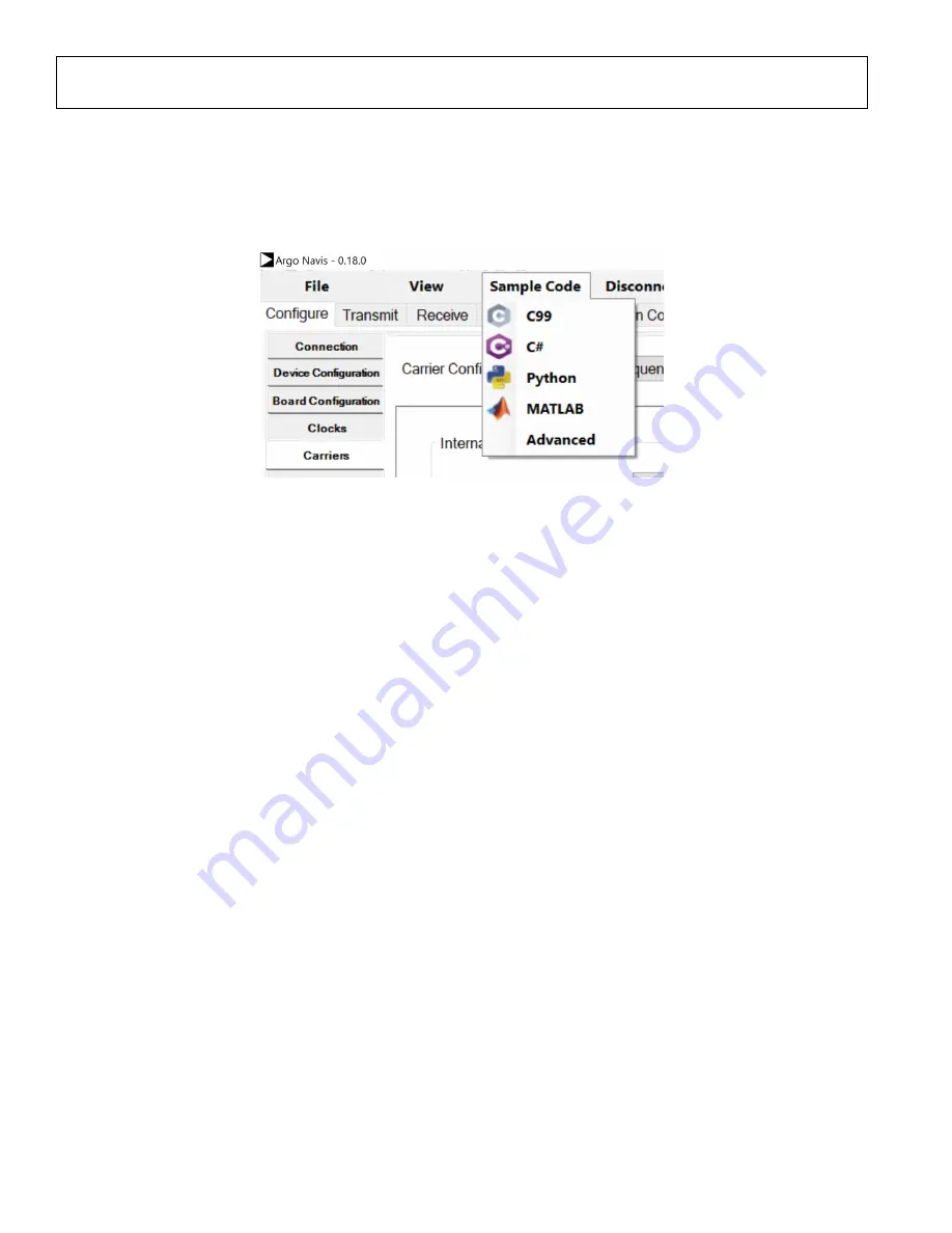
User can use Matlab and Python to initialize their system. First connect PC to the part by clicking on
Connect
button. Then configure the
system to the desired state. Then program. After program is successful, in the GUI click
Sample Code-> Matlab / Python/ C99/ C#
to
generate Matlab, Python, and C initialization code. User can then execute the generate Matlab Python or C code to bring the part to the
same desired state as GUI did. Note before executing the generated code from their platform, the user should
Disconnect
the board in
the TES GUI.
Figure 328. Auto Generated Code Options
EVALUATION SYSTEM TROUBLESHOOTING
The following is a quick help guide describing what to do if the system is not operational. This guide assumes that the user followed
instructions and assembled his setup according to hardware configuration described in this document.
TES Connection Issues
1. Ethernet connection (firewall on IP address, port blocked, etc.)
a. Make sure your firewall settings allow communication to the Xilinx platform.
b. Check that the IP address for the ethernet is set correctly. With a direct connection to the PC the IP address in the TES
should be 192.168.1.10 port 55557 and the LAN connection should be set to 192.168.1.2. With an indirect connection to
the PC the IP address should be set to IP address that the router has dynamically assigned to the FPGA.
2. FPGA platform incorrectly configured (refer to user guide for jumper settings)
a. Check that the switch on the Xilinx platform is set properly to boot from the SD card. You can find these settings here:
3. SD card not compatible with FPGA platform
a. There is a different SD card image required for the different Xilinx platforms that are supported. ADI provides SD card
imaging software. To find the settings needed revisit SD Card Imaging
4. SD card not compatible with TES version
a. There is an early image required for all SDK version previous to 0.13.0. For SDK releases 0.13.0 or later a new SD card
image is required. This is all taken care of with the ADI SD card imaging SW but should be checked if older versions have
been used before.
No LED Activity (ZYNQ ZC706)
1. Check if the board is properly powered. There should be 12V present at the J22 input, and after powering the Xilinx platform on
(SW1 turned on) the following should be true:
a. Fan on the ZYNQ platform is activated. Ensure that fan cable is reconnected to ADRV9001 evaluation platform fan header
P702.
b. A number of green LEDs on the ZYNQ platform near SW1 are ON with no red LEDs active on the ZYNQ platform
c. ZYNQ GPIO LEDs follow the sequence described in the Hardware Operation section.
d. Two green LEDs (D801 and D901) on the ADRV9001 evaluation card should be ON.
2. If the LED sequence does not follow the described one, check jumper settings and SW11 positions on the ZYNQ platform. If
these are correct, check if the SD card is correct and properly inserted in the J30 socket. The user should use the SD card
supplied with the evaluation kit.
3. If there is still a problem and the user is certain that the ZYNQ platform is operational, contact an ADI representative for help.


